A small metallic particle that had contaminated a product line was brought to SI’s Materials…
Metallurgical Lab Case Study: Corrosion Fatigue in WaterWall Tubes
Increasingly A Safety Concern as Coal Plants Cycle
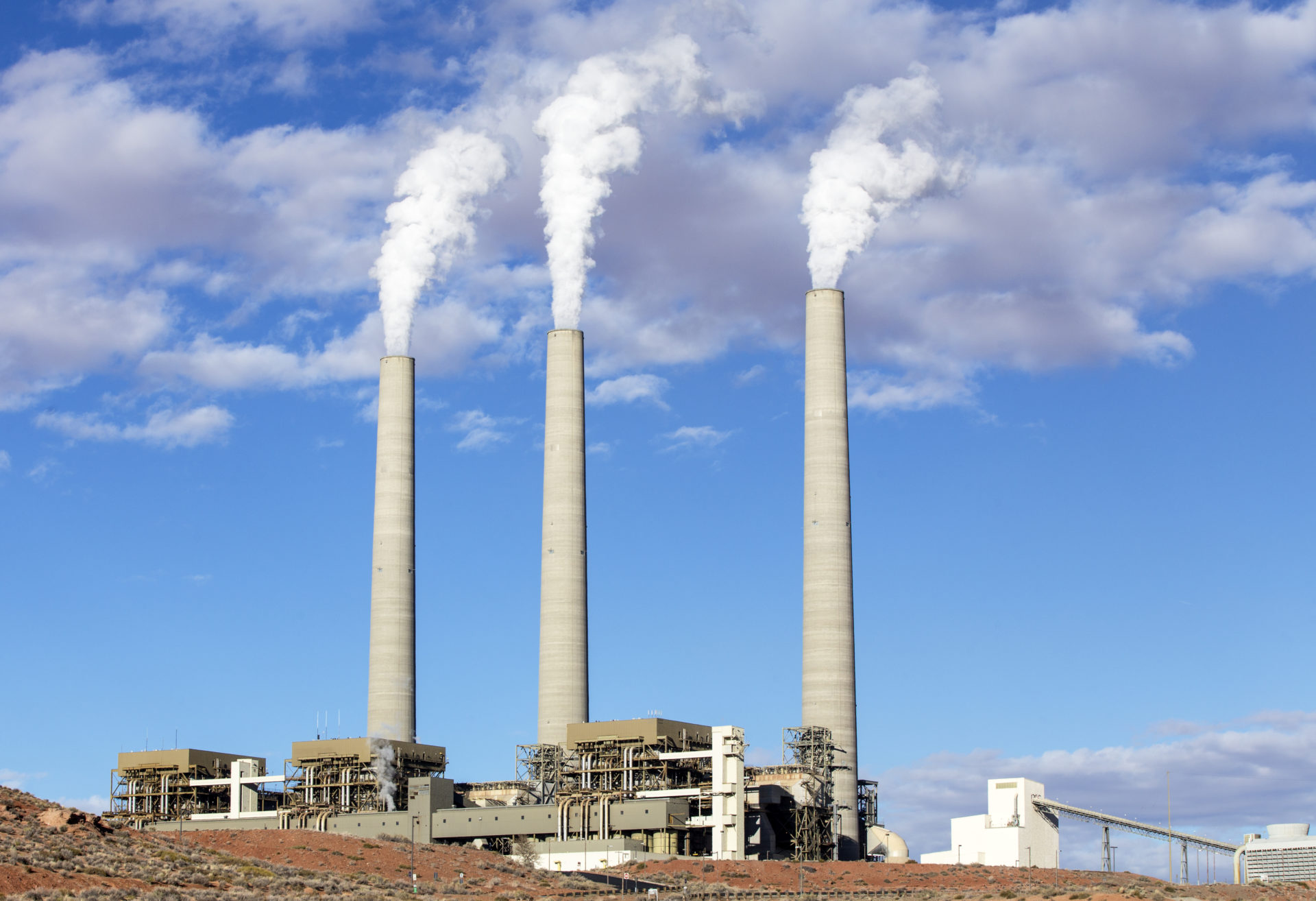
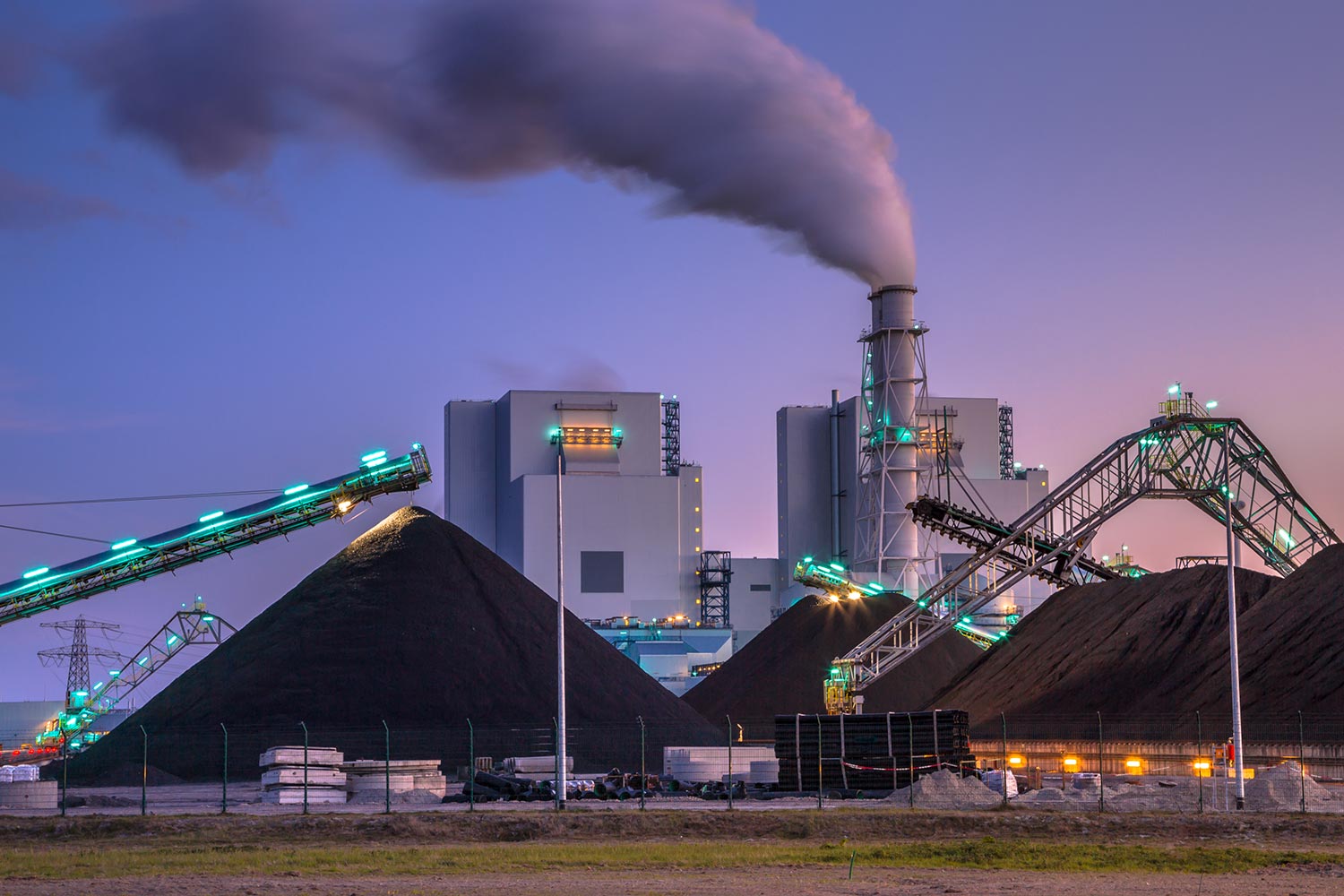
It is well known that conventional coal-fired utility boilers are cycling more today than they ever have. As these units have shifted to more of an ‘on-call’ demand they experience many more cycles (start-ups and shutdowns, and/or significant load swings) making other damage mechanisms such as fatigue or other related mechanisms a concern.
The most recent short-term energy outlook provided by the U.S. Energy Information Administration (EIA) indicates the share of electricity generation from coal will average 25% in 2019 and 23% in 2020, down from 27% in 2018. While the industry shifts towards new construction of flexible operating units, some of the safety issues that have been prevalent in the past are fading from memory. The inherent risks of aging seam-welded failures and waterwall tube cold-side corrosion fatigue failures are a case in point. It is well known that conventional coal-fired utility boilers are cycling more today than they ever have. As these units have shifted to more of an ‘on-call’ demand they experience many more cycles (start-ups and shutdowns, and/or significant load swings) making other damage mechanisms such as fatigue or other related mechanisms a concern. The following case study highlights this point by investigating a cold-side waterwall failure that experienced Corrosion Fatigue. While this failure did not lead to any injuries, it must be stressed that the potential for injuries is significant if the failure occurs on the cold-side of the tubes (towards the furnace wall).
1.0 INTRODUCTION
Structural Integrity Associates, Inc. (SI) was recently asked to investigate the failure of a waterwall tube and to provide recommendations, as necessary.
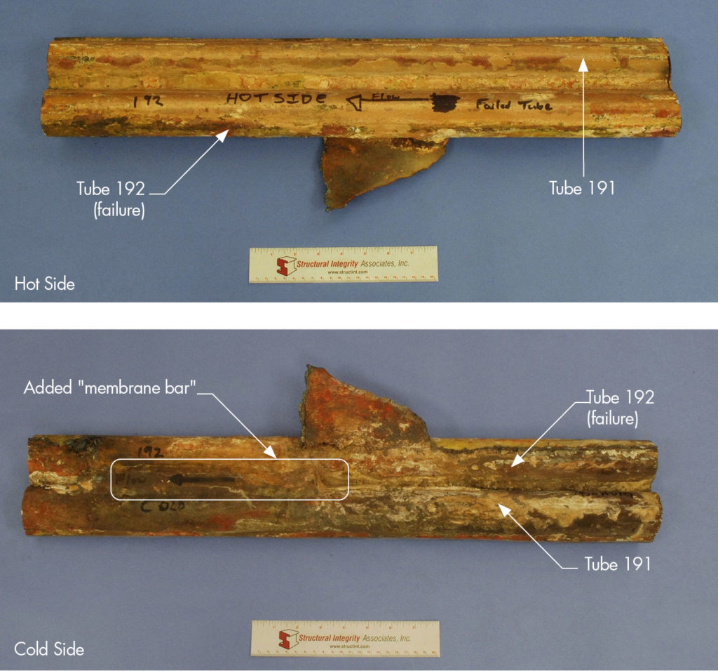
Multiple tubes were examined, including one that contained the failure. They were specified as SA-192 carbon steel (CS) material with dimensions of 2.00” outside diameter (OD) x 0.220” specified minimum wall thickness (MWT). The tube that failed was the last tube of the right sidewall (sidewall tubes are connected via tube-to-tube solid membrane) and the cold side waterwall tube casing reportedly attaches via seal weld to this last tube (similar on the left sidewall).
2.0 EXAMINATION PROCEDURES AND RESULTS
2.1 Visual Examination
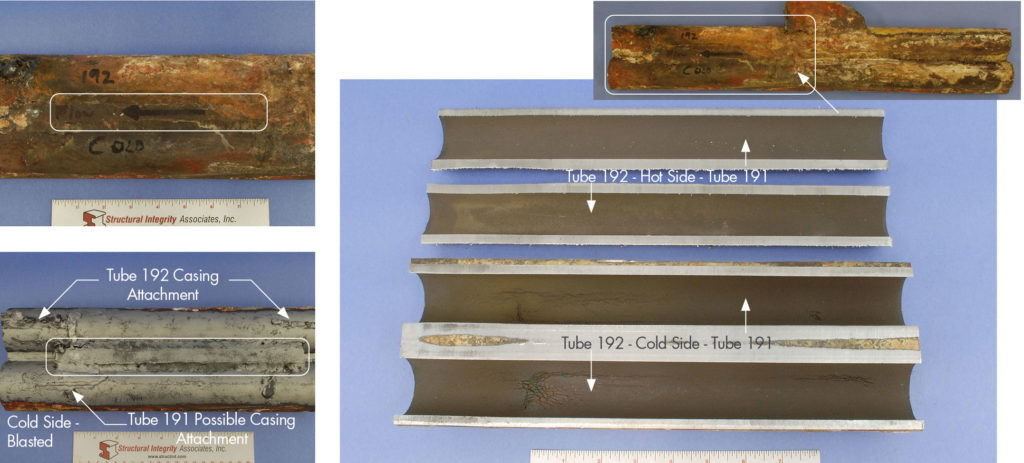
Figure 1 shows the tubes (Tube 191 and Tube 192) in the as-received condition. An annotation by plant personnel notates Tube 192 as the failed tube, although the specific region of failure was not noted. The waterwall tubes are adjoined via membrane weld; however, on the cold side an added “membrane bar” ~10” in length was noted. This “membrane bar” was not fully fused to the tube-to-tube membrane weld, so a gap between the two was present. To facilitate a better examination of the cold side, the tube was grit-blasted to remove the deposits/oxides along the OD surface. Figure 2 shows photographs of the cold side before and after-blasting. A significant number of pad welds, attachment welds, etc. were noted along the cold side OD surface. External or cold side casing attachment points for Tube 192 were confirmed by plant personnel. However, it was unclear if the regions notated for Tube 191 were also attachment points to the casing.
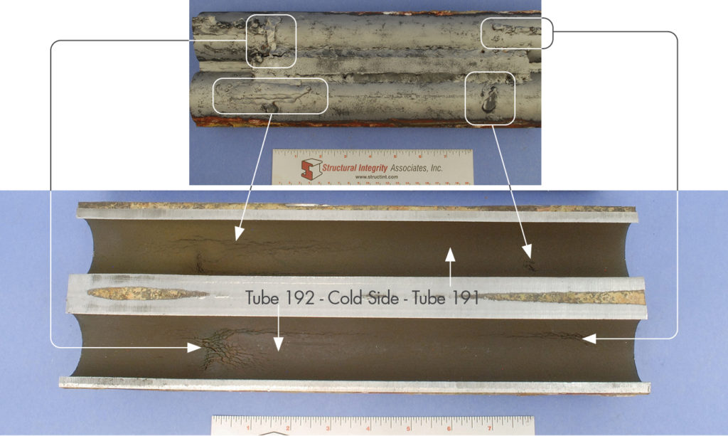
A review of the internal surface prior to sectioning identified indications along an ~14” length of tubing (noted in Figure 3). The tubes were sectioned in this region along the neutral axis (original tube-to-tube membrane weld). The ID surface along the cold side for both tubes exhibited a multi-array of cracking with Tube 192 exhibiting more extensive damage. A number of parallel cracks oriented in both the longitudinal and circumferential directions were observed and appear directly related to the stress field developed as a result of the welds on the cold side OD surface of both tubes. Figure 4 shows photographs correlating the pad/attachment welds on the cold side OD surface of both tubes to the damage on the ID surfaces.
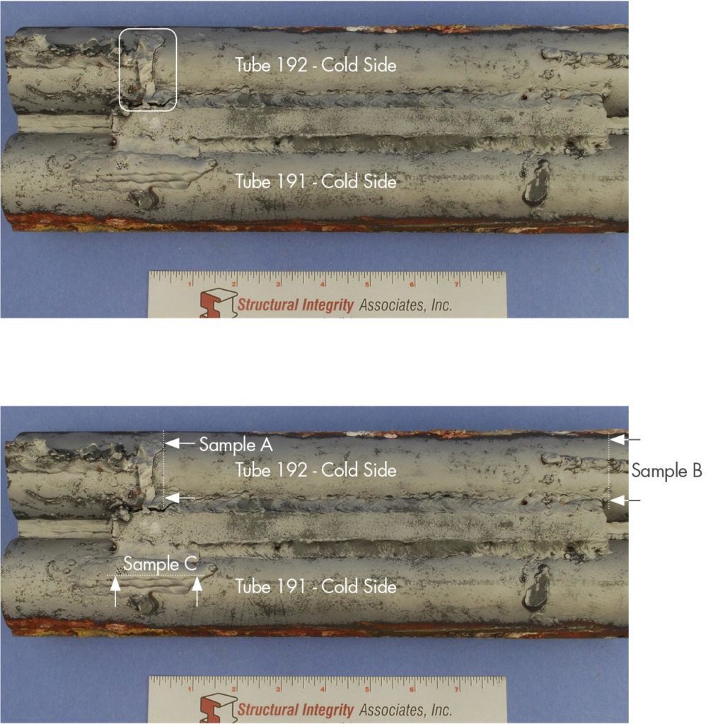
To help identify the actual leak location, a soap solution was applied to the cold side OD surfaces and pressurized air was applied against the cold side ID surfaces. The leak location was identified on Tube 192 at the location shown in Figure 5.
2.2 Metallographic Evaluation
Figure 6 contains macrophotographs of 3 separate metallurgical cross-sections removed from the cold side of both tube sections.
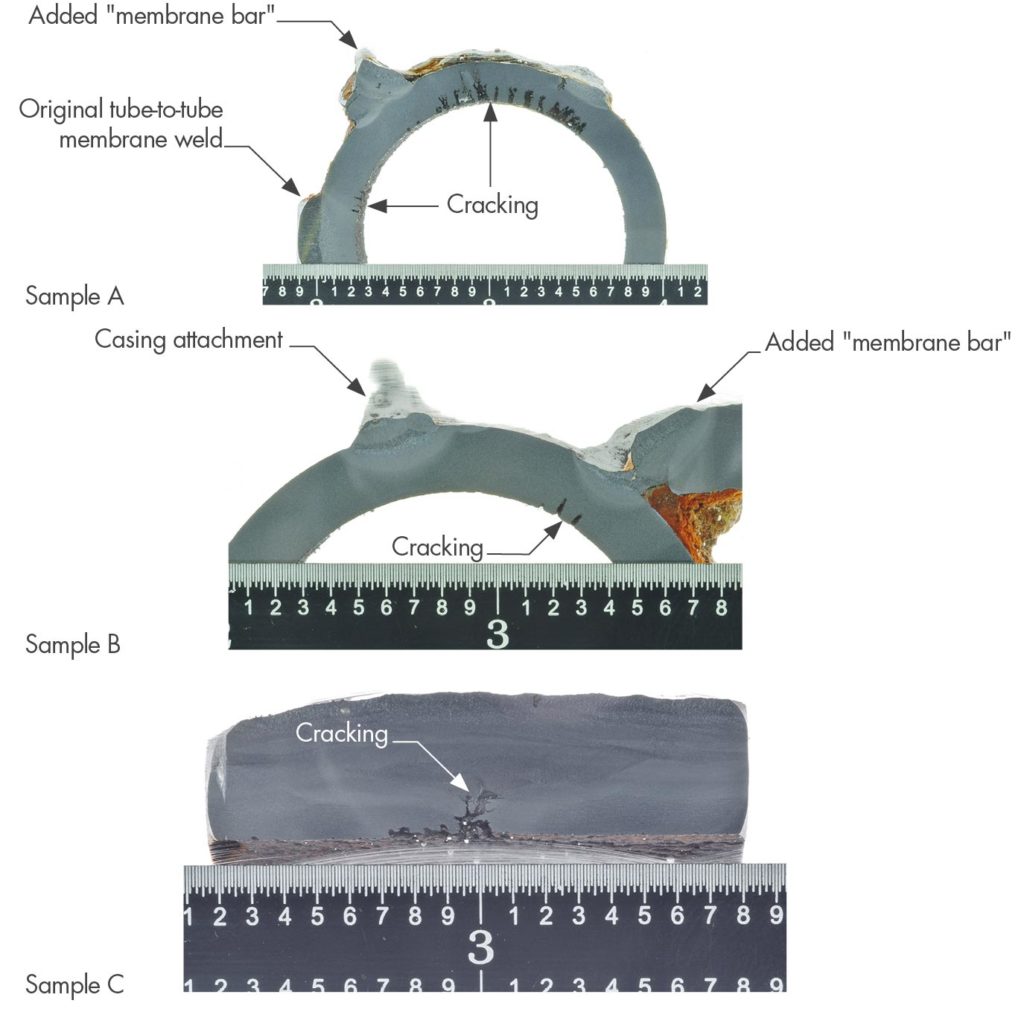
Sample A –
Circumferential cross-section through the identified leak (Tube 192)
Sample B –
Circumferential cross-section through damage, but remote from the failure
(Tube 192)
Sample C –
Longitudinal cross-section through pad weld (Tube 191)
All of the cross-sections revealed cracking emanating from the ID surface. Sample A exhibited extensive and distinct cracks along the cold side crown at approximately the same circumferential zone where the circumferential weld is located on the OD surface/adjacent to the added “membrane bar”. In addition, cracking was noted along the original tube-to-tube membrane weld on the cold side. Sample B exhibited obvious cracking adjacent to the added “membrane bar” on the cold side. No damage was noted in proximity to the casing attachment weld. Sample C exhibited obvious cracking underneath the pad weld.
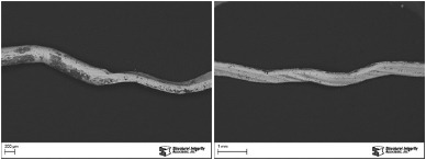
Figure 7 contains an overall stitched photomicrograph of Sample A from Tube 192 documenting the through-wall location. This location exhibited typical crack profiles representative of corrosion fatigue with signs of discontinuous growth via corrosion bulges. Copper deposits were also noted. At the through-wall location it appeared that the damage progressed to ~90% of the local wall thickness before failure resulted.
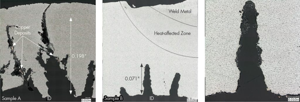
Figure 8 contains an overall stitched photomicrograph of Sample B at the deepest location. This location exhibited typical crack profiles representative of corrosion fatigue with signs of discontinuous growth via corrosion bulges. Minor amounts of copper deposits lined the crack and ID surfaces. At the deepest point, the damage progressed to ~35% of the local wall thickness. These cracks were in line with the added “membrane bar”. A higher magnification photomicrograph of the deepest location from Sample B is shown in Figure 9. The crack is blunt-tipped, contains corrosion bulges, and is lined with deposits/oxides.
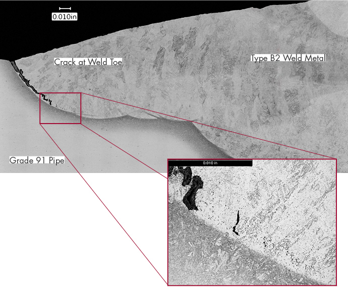
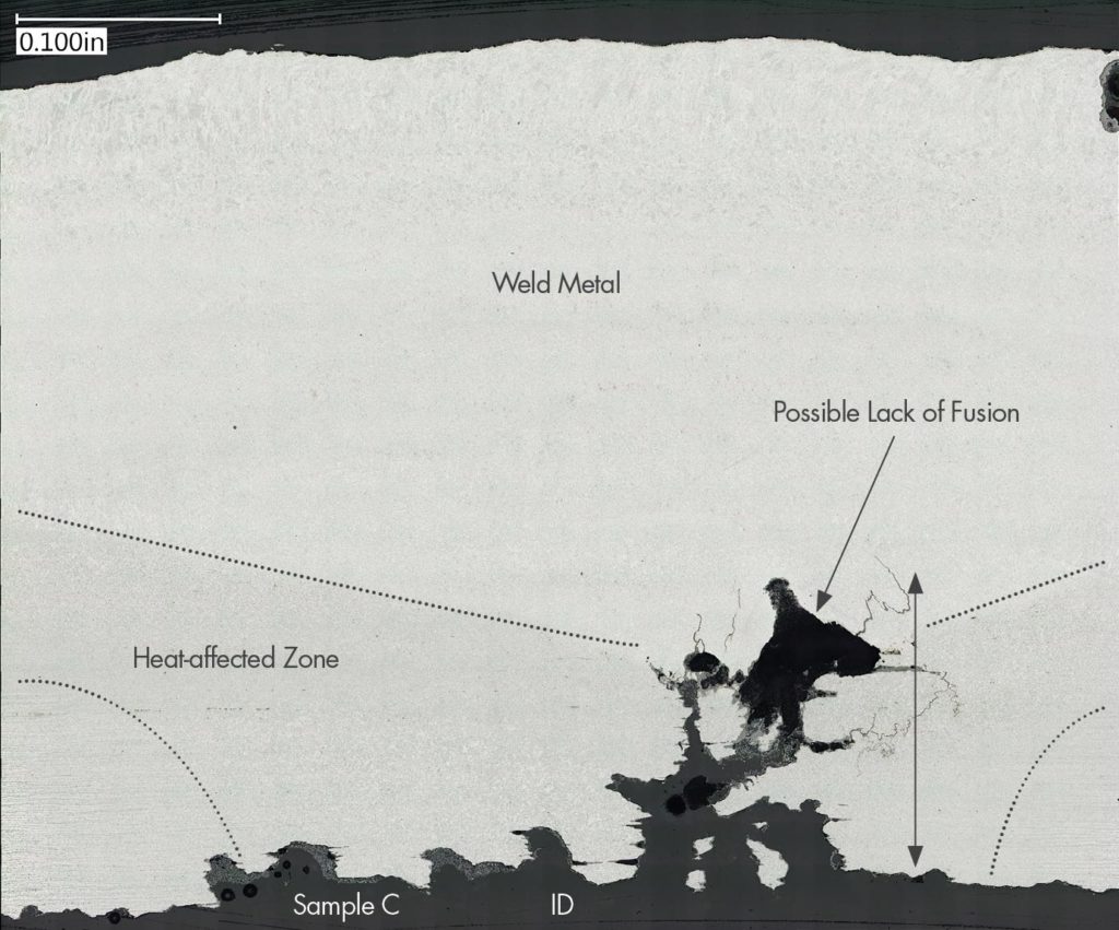
Figure 10 contains an overall stitched photomicrograph of Sample C from Tube 191. This location also exhibited a crack profile representative of corrosion fatigue. At the deepest point, the damage progressed to ~37% of the local wall thickness (note: the pad weld increased the wall thickness to ~0.400”). A significant amount of weld metal is present at this location and could possibly indicate previous repair attempts. The cracking extended through the heat-affected zone (HAZ) until linking with a possible lack of fusion site in the weld metal. In the longitudinal direction, the un-affected base metal exhibited a banded microstructure.
In general, pitting was noted on the ID surface adjacent to damage sites. These incipient pits were lined with deposits/oxides and were less than 10 mils in through-wall thickness. The typical microstructure from Tube 192 cross-sections (Sample A and B), consisted of intact pearlite colonies within a ferrite matrix.
3.0 DISCUSSION
Tube 192 failed as a result of extensive corrosion fatigue (CF) damage on the cold side of the tube that initiated from the ID surface. Each tube exhibited a significant number of pad welds, attachment welds, membranes, etc. scattered along the OD surfaces of the cold side. Along the ID of Tube 192 a multi-array of cracking was noted with a number of parallel cracks oriented in both the longitudinal and circumferential directions and appear directly related to the stress field developed as a result of the welds on the OD surface. Significant cold side damage was also noted for the adjacent tube (Tube 191).
No apparent damage was noted on the hot side ID surfaces for either tube. Crack morphologies exhibited discontinuous growth via corrosion bulges along the length of each crack. Oxides/deposits (including copper) lined the crack surfaces. Adjacent to the damage sites incipient pitting was observed typically less than 10 mils in through-wall thickness and were also lined with oxides/deposits.
CF is a discontinuous cracking mechanism, whereby the cracks propagate through the tube wall by a repetitive oxide fracture process. The magnetite that grows indigenously on the inside tube surface is a protective oxide, unless it is subjected to strains in excess of its fracture strain (about 0.2%). During normal full load operation the strain in the tube is very low, and only during certain operating regimes does the strain locally increase due to the restriction in expansion caused by membrane and attachment welds. Experience has shown that these regimes may be related to operational regimens (startup, shutdown, forced cool, transient operation, trips) or due to mechanical loading by other boiler equipment (coal pipes, burner equipment). These operating regimes are referred to as the “operating space”, and the key to solving CF is to identify the harmful operating space and modify that space so that the imposed strain is below the fracture strain. The best way to identify the operating spaces and thus to solve the problem is to instrument a couple of key CF locations with thermocouples and strain gauges and to monitor these as the unit is operated through the operating spaces. The boiler chemistry is also known to exacerbate the CF mechanism and rate, with the most important parameter being the reduction in the boiler water pH from normal operating ranges. Situations in which the pH is depressed while peak strains are imposed on the oxide are particularly harmful and need to be identified.
3.1 Recommendations
It is extremely important that plant personnel clearly identify the geography and history of failures over time. At this junction, it may be prudent to inspect visually the casing side and the ID with borescope at a similar elevation as this failure on the other four corners of the boiler. Drawings/information identifying other casing attachment points at other elevations would also be good locations to inspect, as well. These can help determine if the “attachments” for this particular location were correct or altered at some unknown date.
A replacement in-kind will always help remove the current damage, but mitigation of the problem is not ensured. Damage accumulation is heavily dependent on how the “operating space” at the plant has evolved over the years. A selection of pertinent locations for monitoring temperature/strain history using thermocouples and strain gauges will help gauge damage accumulation rates and whether transients can be adjusted to help lower the fracture strain.
Of equal importance, cycle chemistry should be monitored to ensure that pH levels are not depressed during transient operation.
Ultimately, through some of these items it may be determined that operational conditions and/or the mechanical loading (attachments, etc.) of the tubes will require modifications.
Related Posts