A small metallic particle that had contaminated a product line was brought to SI’s Materials…
Example Grade 91 High Energy Piping DMW Joint Stress & Metallurgical Analysis
Determining a course of action once in-service damage is discovered often requires applying a multi-disciplinary approach that utilizes Nondestructive Examination (NDE), analytical techniques such as stress analysis, and metallurgical lab examination. Such was the case recently for a combined cycle plant where indications were found through NDE on the inlet sides of two identical main steam stop/control valves but were not seen on the outlet side. In this case, Structural Integrity (SI) did not perform the field NDE but was requested to perform analytical and metallurgical assessments of the welds. The welds in question joined the 1Cr-1Mo-1/2V (SA-356 Grade 9) main stop/control valve body castings to Grade 91 piping, so the welds represent a ferritic-to-ferritic dissimilar metal weld (DMW). The welds were made using a 1Cr-1/2Mo (AWS type B2) filler metal, which matches the chromium content of the valve body, but is significantly undermatching strength to both the valve body material and the Grade 91 piping. The course of action taken was to perform local stress analysis and remaining life estimates for the downstream (outlet) connections of the valves to assess the likelihood of future damage and establish an appropriate re-inspection interval. A detailed metallurgical analysis was also performed on a ring (entire circumference) section removed from one of the upstream welds (which exhibited both surface and volumetric indications in the weld metal) in order to provide insight into the damage mechanism and inform the stress analysis and remaining life estimates.

Metallurgical Analysis of Upstream (Inlet) Weld
The ring section was subjected to an initial visual and magnetic particle inspection, which revealed surface indications that were not detected or reported during the third-party NDE performed on site; the extent and appearance of these indications are shown in Figures 1 and 2.

Figure 1. Schematic of upstream weld ring section illustrating the extent of crack-like surface indications found in laboratory visual and magnetic particle inspections. The circumferential locations of four metallographic sections removed from the ring are also noted.
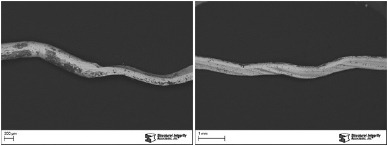
Figure 2. Close views of crack-like visual indications on the weld surface at two circumferential locations. Cracks were found at both weld toe and at the centerline of the first weld bead.
Metallographic sections were prepared through the weld at the four circumferential locations noted in Figure 1. Examination of the sections identified two separate damage mechanisms: reheat cracking occurring in the large columnar grains at the centerline of the surface weld deposit, command creep damage in the weld deposit adjacent to a carbon-depleted region along the fusion line. Microchemical analysis by energy-dispersive x-ray spectroscopy in the scanning electron microscope (SEM-EDS) confirmed that the weld metal deposit was indeed a type B2 material (1Cr-1/2Mo), while the pipe base metal was Grade 91 (9Cr-1Mo-V-Nb). Figure 3 shows a macroscopic overview of one of the sections; Figure 4 shows a closer view of creep-related weld toe cracking in another section.

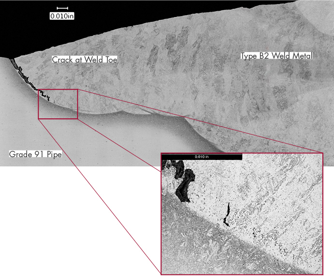
Figure 3. Overview of the metallographic section prepared at the 18” circumferential location, with creep-related cracking present at the weld toe, in the first weld bead, and along the fusion line. Creep cracking in the first weld bead likely developed from fabrication-related reheat cracks.
Evidence for reheat cracking was found in the form of intergranular cavitation and cracking in the surface weld beads. In some areas it appears these cracks acted as initiation sites Metalfor in-service creep cracking (Figure 3). Reheat cracking is related to original fabrication, with the cracking likely occurring during post-weld heat treatment rather than in service. This damage mechanism is not common for the B2-type filler metal but is possible, particularly given the large columnar grain structure in the weld deposit.
Creep-related fusion line cracking is common for welds between ferritic materials with dissimilar chromium content. The chromium gradient drives carbon migration from the lower-chromium material to the higher-chromium material, creating a weaker, carbon-depleted region in the lower chromium material, which in this case is the weld deposit. See the Dissimilar Metal Welds in Grade 91 Steel, (page 15) for further information. A corresponding carbon-enriched zone forms in the higher-chromium material. Creep damage will preferentially form in or immediately adjacent to the carbon depleted zone due to the local strength mismatch between the depleted and non-depleted materials (Figure 4). The carbon migration and consequential creep damage results from service exposure at normal operating temperatures (~1040°F). The degree of carbon migration was typical for a weld between Grade 91 and B2-type (1Cr-Mo) filler metal that has experienced approximately 90,000 hours of service.

Figure 4. Creep-related cracking at the weld toe in the 26.5” orientation. Cavitation damage was present in the weld metal adjacent to the fusion line ahead of the crack tip (inset photo).
Creep damage associated with the carbon-depleted zone is the fundamental damage mechanism that will control the life (failure time) of such ferritic dissimilar metal welds. In this case, the creep-damaged region (cavities and linkage to macro-cracking) represents approximately 15% of the wall thickness. As a result, this weld could have endured some continued service before cracking would have extended fully through the wall and resulted in a steam leak. When performing life assessment of such welds, the region of creep-weak material adjacent to the fusion line should be included in any analytical models. This is highlighted further in the next section which discusses stress analysis of such welds.
Stress Analysis
After discovery of significant indications on the upstream (inlet) welds to the main steam stop/control valves as documented in the metallurgical section above, a detailed stress analysis and lifetime prediction was requested for the downstream (outlet) welds. Detailed creep-redistributed stress analysis was performed using a finite element model geometry that was based on field measurement of the thickness profile from the valve body to the transition piece. The finite element model accounted for the different creep strengths of the various materials associated with the weld joint, in particular the lower strength of the B2-type weld deposit and the carbon-depleted zone which forms adjacent to the weld fusion line between the weld deposit and the Grade 91 pipe. The calculation results (Figure 5) indicated that the creep deformation of the weaker weld deposit would be constrained by the stronger surrounding Cr-Mo-V and Grade 91 materials, and under internal pressure alone the lifetime for the downstream weld was predicted to be approximately 150,000 hours, accounting for the effects of carbon migration.
This is consistent with the lack of damage found in third-party NDE of the downstream welds. Detailed numerical analysis of the upstream weld was not performed as part of this study, but based on the geometric differences between the upstream and downstream welds, the stress in the upstream weld was estimated to be approximately 10% higher than that in the downstream weld (potentially even higher if there were additional axial system stress). This suggests, based on creep rupture data, the upstream weld would have approximately 70% of the life of the downstream weld. Given the downstream weld estimated life of 150,000 hours, the estimated lifetime of the upstream weld would be approximately 100,000 hours, similar to the stated operating time of ~90,000 hours at which extensive cracking was present.
These calculations suggest damage in the upstream weld was very likely (life fraction nearly fully consumed), whereas the downstream weld had reached a life fraction of approximately 70%. Hence some indications (creep damage) are likely at the downstream weld, but these may have not linked to form a macroscopic crack, consistent with the lack of NDE indications for this weld.

Figure 5. FEA output showing spatial distributions of creep-redistributed von Mises equivalent stress top and maximum principal stress bottom in the modeled weldment.
Discussion
This is an interesting case study because the transition between the valve body and piping included a tapered transition piece to bridge the thickness differential between the valve body and piping. On the face of it, that would be regarded as “good practice”, particularly since failures at other similar connections have been exacerbated by the lack of a transition piece leaving the weld deposit to bridge the thickness differential. Hence, even with a transition piece, the connection is vulnerable because of the carbon migration that occurs as a result of the difference in chromium content, in this case between the weld deposit and transition piece. The use of a significantly under-matched filler metal (type B2) does not help in this case. While the filler metal is constrained by the stronger surrounding material, the triaxial stresses that result from creep stress redistribution promote creep damage formation.
The primary mitigation in the present case, would be to remove the B2-type (1Cr-1/2Mo) weld deposit and replace it with a B9-type (9Cr-1Mo-V-Nb) deposit on the upstream and downstream welds. This would remove any prior creep damage and local carbon migration. The use of B9-type filler metal provides a closer strength match to the piping and valve body, although a chromium differential still exists on the valve side of the weld deposit. So this weld remains vulnerable to failure, but the closer match in strength will mitigate some stress triaxiality. As a result, such welds should be subject to occasional inspection with an appropriate interval being selected from creep redistributed stress analysis and subsequent lifing based on a similar approach to the stress analysis described earlier.
This case study also highlights indications can be missed during routine NDE. In this case it appears surface preparation techniques may have contributed to masking of damage. This is why use of a grit-blasting surface preparation technique should be adopted (versus wire-wheel), and this should be accompanied by use of wet fluorescent magnetic particle testing (WFMT) which provides good sensitivity to oxide-filled cracks in components that operate at high temperature. Inspection should also include use of linear phased array (LPA) ultrasonic techniques since subsurface cracking is likely in such welds.
More generally, the life of such ferritic dissimilar welds is significantly reduced by higher stresses acting across the weld, directly stressing the weaker carbon denuded region. For that reason it is always prudent to have a detailed creep redistributed stress analysis for piping systems that operate in the creep range; this provides accurate estimates of cross-weld stress can be used in lifing calculations. This should obviously be accompanied by occasional pipe support surveys to ensure the piping system movement is consistent with the stress analysis.
Related Posts