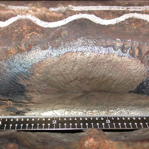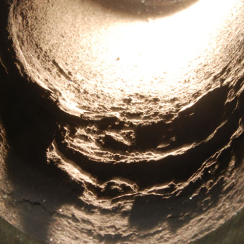
Heavy deposits on ID surface
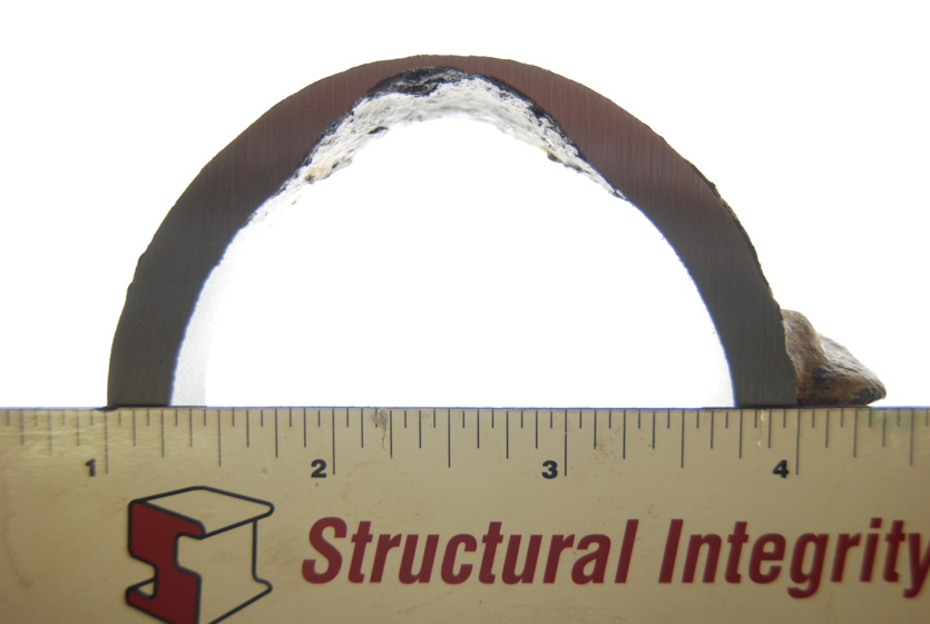
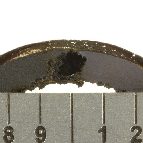
Cross-section through gouge on ID surface
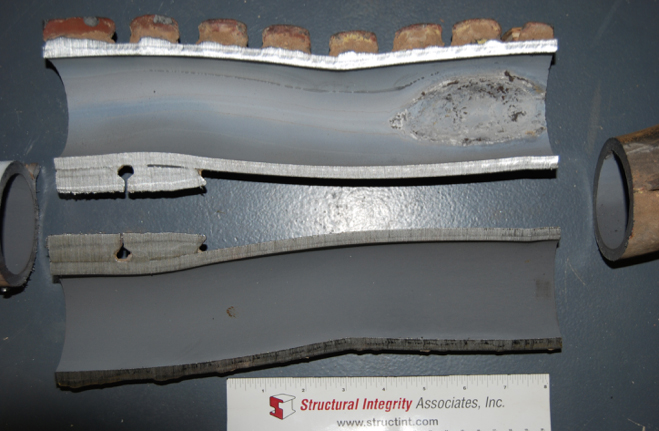
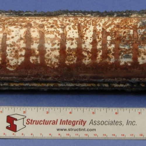
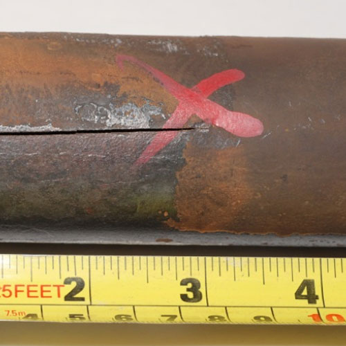
Gouge on ID surface near bend
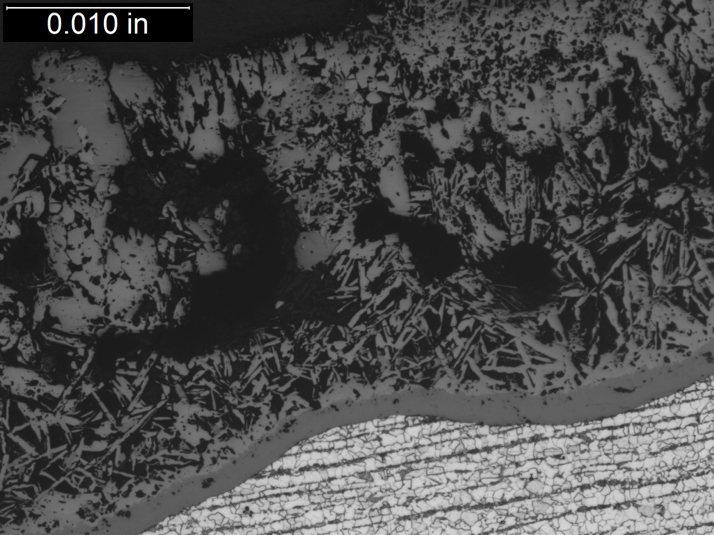
Needle-like Crystals Observed in Caustic Gouging Deposit
Caustic Gouging
Introduction
Caustic gouging (CG) is an underdeposit corrosion (UDC) mechanism that has begun to increase in frequency in recent years at some fossil plant boilers and at combined cycle plants with heat recovery steam generators (HRSGs). Caustic gouging occurs in the presence of heavy tube deposits and sodium hydroxide that concentrates at the tube surface.
Description
Mechanism
Caustic gouging requires a buildup of internal deposits along with a concentration of contaminant. The contaminant in this case is sodium hydroxide. Damage begins with the transfer and deposition of corrosion products in the boiler. Thermal-hydraulic conditions increase the concentration of caustic in the deposits. This concentrated caustic dissolves the protective magnetite layer, which leads to the formation of sodium iron oxides (sodium ferroate and sodium ferroite). The corrosion rate increases and final failure occurs when the reduced tube wall thickness can no longer support the internal pressure.
Typical Locations
- ID surface of hot side of tubes
- Highest heat flux areas
- Near flow disruptors: joints, bends, protruding welds, etc.
Features
- Waterside mechanism
- Pinhole leak or thin-edged failure
- Gouging on ID surface
- Thick adherent deposits within gouge
- Needle shaped deposits within gouge (Crystals of sodium ferroate or sodium ferroite)
- Sodium detected at base of gouge
- No microstructural changes
Root Causes of Caustic Gouging
Caustic Gouging occurs where high levels of deposits are present and where caustic is present due to the addition of sodium hydroxide or to contaminant ingress containing the sodium ion. Poor feedwater treatment often results in high corrosion product levels. Deposits are most often the result of corrosion or flow-accelerated corrosion in the condensate/feedwater system in conventional plants or in the low pressure part of the HRSG followed by the transport of copper and/or iron into the waterwalls of conventional boilers or into the HP evaporator circuit in HRSGs. Deposition can also be influenced by disruptions in flow in the boiler waterwall tubing or in HRSG evaporator tubing, or it may be promoted by flame impingement and burner misalignment. Ineffective chemical cleaning or incomplete flushing may allow deposits to remain and concentrate. Chemical cleanings which are warranted based on deposit loading are often delayed. Process return streams from offsite steam systems may be another source of both corrosion products and sodium. Excess sodium hydroxide can accumulate when using caustic treatment (>2ppm), phosphate treatment, or with all-volatile treatment when caustic is introduced during startup or during an acidic contamination event to control pH. Other potential sources of sodium include upsets from the makeup water treatment plant or condensate polishers, or sodium hydroxide from the regeneration process. The online chemistry instrumentation must be adequate to identify excessive levels of hydroxide in the boiler/evaporator water and alert operations personnel to the high levels.
Corrective Actions
Widespread caustic gouging can be detected using ultrasonic techniques to identify areas with heavy wall loss. Failed tubes should be metallographically analyzed to confirm the failure mechanism. After the mechanism is confirmed, the root cause of the damage should be identified. The plant cycle chemistry should be reviewed and optimized to prevent future damage.
Damaged tubes can be replaced after they have been located. Pad welding should not be used to repair damaged tubes, as excessive penetration of the weld can lead to flow disruptions and reinitiate the damage. Chemical cleaning is recommended to remove heavy deposits.
SI Services for Caustic Gouging in Conventional Fossil and Combined Cycle Plants
- NDE/inspection services to define the geography of damage using visual inspection for HRSGs and ultrasonic testing (UT) for conventional boilers.
- Provide recommendations for appropriate tube sampling locations for both conventional boilers and HRSGs. Conduct proactive assessments of deposits in tubes.
- Mechanism identification through metallurgical analysis of affected tubing, to include a determination of the morphology of the internal indigenous oxide and deposits. Identification of sodium iron oxides within the deposits and the absence of the protective magnetite layer are key indicators of caustic gouging damage.
- Plant cycle chemistry program review and FAC assessment and benchmarking, typically completed during a one day site visit. Assess plant practices with respect to the number of repeat situations that can increase the likelihood of caustic gouging. Provide a suggested action plan to address deficiencies in the chemistry program and repeat situations to include monitoring of feedwater corrosion products and instrumentation to adequately monitor chemistry around the cycle. Provide suggestions on the proper water treatment program for the boiler walls and HRSG evaporators (HP/IP).
- Provide guidance on the proper operation of caustic water treatment, including monitoring, chemical feed, instrumentation alarms, and out of specification response.
- Support the implementation, review and follow-up of the action plan and assess the results. Provide support and guidance to effectively clean the boiler or HP evaporator circuit to remove deposits.
- Provide advice and guidance on repair activities.
Additional information
| Boiler Type | |
|---|---|
| Fuel | |
| Boiler Region | |
| Metallurgy | |
| Failure |