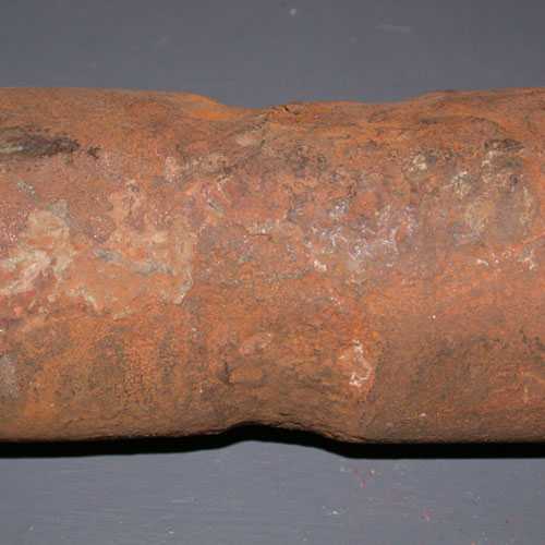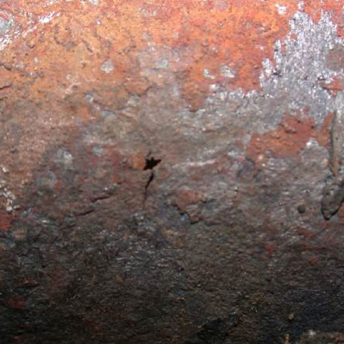
Pinhole leak on OD surface of waterwall tube
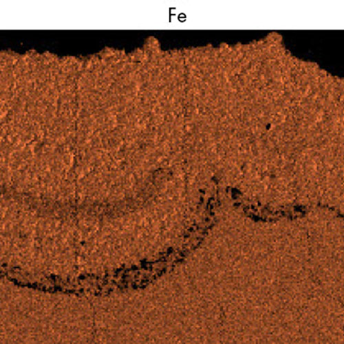
Fe
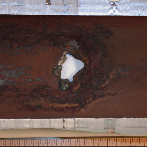
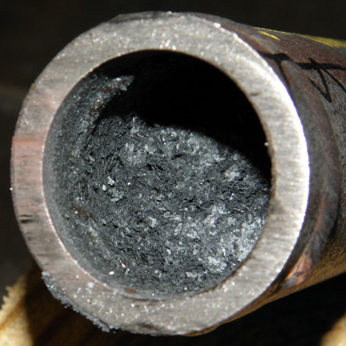
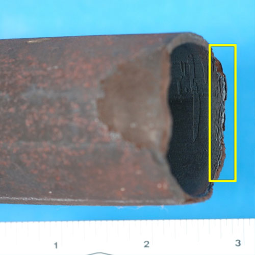
Gouging on ID surface of waterwall tube due to ACP
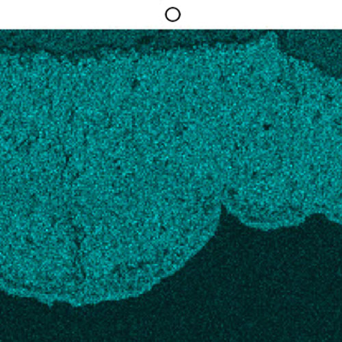
O
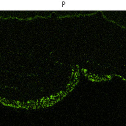
P
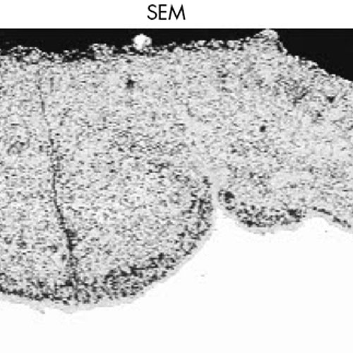
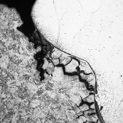
SEM
Acid Phosphate Corrosion
Introduction
Acid Phosphate Corrosion (APC) is one of the three major underdeposit corrosion (UDC) mechanisms that has been encountered in recent years at many fossil plant boilers as well as at combined cycle plants with heat recovery steam generators (HRSGs).
Description
Mechanism
APC requires the combination of heavy internal deposits with a concentration of phosphate when using mono-sodium or di-sodium phosphate water treatment. These chemical phosphate blends have sodium to phosphate ratios lower than 3:1. Thermal-hydraulic conditions such as steam blanketing or wick boiling increase the concentration of phosphates in the deposits and lead to fluxing of the protective magnetite layer and in some cases the actual metal surface. Sodium phosphates exhibit retrograde solubility, which is a decrease of solubility with increasing temperature.
Reaction products will include maricite (NaFePO4), which forms when magnetite reacts with mono- or di-sodium phosphate. Maricite is a key indicator of the acid phosphate corrosion mechanism. Once the local corrosive environment is formed, a local gouge on the internal surface is created. Final failure occurs when the reduced tube wall can no longer support the internal pressure. The macroscopic appearance is typically a ductile pinhole leak.
Typical Locations
- ID surface of hot side of tubes
- Highest heat flux areas
- Near flow disruptors: joints, bends, protruding welds, etc.
Features
- Waterside mechanism
- Pinhole leak or thin-edged failure
- Gouging on ID surface
- Thick loose deposits within gouge
- Phosphorus (maricite) detected at base of gouge
- No microstructural changes
Root Causes
Acid Phosphate Corrosion occurs where high levels of deposits are present and an acidic phosphate compound is used as part of the boiler water or evaporator water treatment program. Poor feedwater treatment often results in high corrosion product levels. Deposits are most often the result of corrosion or flow-accelerated corrosion in the condensate/feedwater system in conventional plants or in the low pressure part of the HRSG followed by the transport of copper and/or iron into the waterwalls of conventional boilers or into the HP evaporator circuit in HRSGs. Deposition can also be promoted by disruptions to the internal flow in the boiler waterwall or HRSG evaporator tubing or by flame impingement and burner misalignment. Ineffective chemical cleaning or incomplete flushing may allow deposits to remain or concentrate. Chemical cleanings which are warranted based on deposit loading or in combination with a significant phosphate hideout are often delayed. Process return streams from offsite steam systems may be another source of both types of corrosion product. The phosphate component may result from operating with too high a phosphate concentration, improper chemistry controls, the chasing phosphate hideout, or the use of a mono- and/or di sodium phosphate or a proprietary blend with a sodium-to-phosphate molar ratio below 3:1.The online chemistry instrumentation must be able to identify and alert operations personnel to phosphate hideout and pH depression.
Corrective Actions
APC can be detected using ultrasonic techniques to identify areas with heavy wall loss. Failed tubes should be metallographically analyzed to confirm the failure mechanism. After the mechanism is confirmed, the root cause of the damage should be identified. The plant cycle chemistry should be reviewed and optimized to prevent future damage.
Damaged tubes can be replaced after they have been located. Pad welding should not be used to repair damaged tubes, as excessive penetration of the weld can lead to flow disruptions and reinitiate the damage. Chemical cleaning is recommended to remove heavy deposits.
SI Services
- NDE/inspection services to define the geography of damage using ultrasonic testing (UT) for conventional boilers and using fiber optic or other visual techniques for HRSGs.
- Provide recommendations for appropriate tube sampling locations for conventional and HRSGs. Proactive assessments of deposits in tubes can also be conducted.
- Mechanism identification through comprehensive metallurgical analysis of the failure areas and/or characterization of the morphology of the internal indigenous oxide and deposits. Identification of maricite within the deposits confirms APC.
- Plant cycle chemistry program review, typically completed during a one day site visit. SI also can assess plant practices with respect to the number of repeat situations that can increase the likelihood of APC. SI will provide a suggested action plan to address deficiencies in the chemistry program and repeat situations to include monitoring of feedwater corrosion products and instrumentation to adequately monitor chemistry throughout the cycle. SI also will provide suggestions on the proper water treatment program for the boiler water and HRSG evaporators (HP/IP).
- Support the implementation, review and follow-up of the action plan and assess the results. Provide support and guidance to effectively clean the boiler or HP evaporator circuit to remove deposits.
- Provide advice and guidance on repair aspects.
Additional information
| Boiler Type | |
|---|---|
| Fuel | |
| Boiler Region | |
| Metallurgy | |
| Failure |