A small metallic particle that had contaminated a product line was brought to SI’s Materials…
Metallurgical Lab – Dissimilar Metal Welds (DMW) in Boiler Tubing: The Need for Confirmation
As plants age, the need for inspection for service related damage to ensure unit reliability increases. There are several approaches that plants can take to reduce the risk of premature failures and proactively manage their DMWs. First is metallurgical sampling. Based on temperature profiles across the boiler, operating conditions, and operating history, DMWs can be selected for laboratory analysis. This will provide some insight into possible damage accumulation; however, the better approach, if damage is suspected, is to perform an ultrasonic inspection of the DMWs. This allows inspection of all the DMWs, and only requires access and surface preparation. If indications are detected, then tube sampling should be performed.


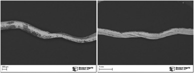
Figure 1. Cross sectional views showing creep damage observed in a friction DMW (Etchant: Nital).
It is critical to perform a metallurgical analysis of several of the DMWs suspected of containing service damage to confirm that the indications are service related and to help establish the extent of the damage compared to ultrasonic testing results. Typical DMW damage is described in the Featured Damage Mechanism article. The importance of the metallurgical analysis is demonstrated in the three following case studies.
Case 1
The boiler had been in service for about 260,000 hours when it experienced a DMW failure. The failed tube was submitted for laboratory analysis, which confirmed the failure was due to creep. Figure 1 shows a cross sectional view of the creep fracture across the DMW and a higher magnification view of the extensive creep damage in the ferritic material adjacent to the fusion line.


Figure 2. LEFT LPA images shows scans from a 25% – 50% classifications. RIGHT <25% classifications
Based on the observed creep damage, the decision was made to perform an ultrasonic inspection of the DMWs during the next scheduled outage. The DMW inspection was performed using linear phased array (LPA) ultrasonic testing. Due to the fact that the DMWs were located in panels, the inspection was limited just to the accessible sides of the tubes. Each DMW was categorized based on the size of the indications relative to the wall thickness. The five categories were no recordable indications (NRI), < 25%, 25% – 50%, 50% – 75%, and 75% – 100% through wall. Over 100 DMWs were inspected and four DMWs were identified as containing indications 25% – 50% through wall and eighteen were identified as containing indications < 25% through wall. No indications were detected in the remaining DMWs. Figure 2 show the LPA images for one of the 25% – 50% classifications and one of the < 25% classifications.

Figure 3. Creep damage observed in the ferritic material along the DMW fusion line (Etchant: Nital).
Four samples were removed for metallurgical analysis: two samples containing indications 25% – 50% through wall, one sample containing indications < 25% through wall, and one sample containing no indications. Each DMW was sectioned longitudinally at four quadrants, 1(12:00, 3:00, 6:00, and 9:00). The cross sections were mounted, ground, polished, and etched using standard laboratory techniques. The prepared mounts were examined using a metallurgical microscope for evaluation of service damage associated with the DMWs. Figure 3 shows the typical creep damage observed in the DMWs. The damage extended in the ferritic material adjacent to the weld fusion line from the external surface.
The metallographic results confirmed the damage was service related and agreed with the extent of the damage detected, as shown in Table 1. In addition, the laboratory analysis revealed more extensive damage in a region inaccessible to the LPA inspection due to the panel configuration.

Table 1. Comparison of LPA Inspection and Metallographic Results for Case 1
Case 2
The boiler was commissioned in 1968. The pendant superheat section consisted of 79 pendants with two tubes in each assembly. Dissimilar metal welds connecting Grade TP347H stainless steel to Grade T22 were located on the outlet leg approximately 12 inches above the roof in the penthouse. A second set of DMWs was located in the boiler, 39 inches and 54 inches above the lower bend. A total of 316 DWMs was inspected in the superheater tubing using LPA. Table 2 summarizes the results of the LPA inspection.

Table 2. LPA Inspection Results for Case 2
Two DMWs were removed from the boiler: one 50%-75% classification and one 75%-100% classification. A DMW from the penthouse with a 50%-75% classifications was also removed. Samples were cut from each DMW at four quadrants and prepared for metallographic examination. Table 3 presents a comparison of the LPA inspection results with the laboratory analysis results.

Table 3. Comparison of LPA Inspection and Metallographic Results Case 2
The LPA classification showed good correlation with the actual amount of creep damage observed in the two DMWs removed from the boiler. The LPA classification for the DMW removed from the penthouse overestimated the actual damage present; however, the DMW contained numerous welding flaws which would also act as signal reflectors. Figure 4 shows lack of fusion and slag inclusions observed in the DMW from the penthouse.


Figure 4. Cross sectional view of the DMW removed from the penthouse. The DMW contained extensive welding flaws. Service related damage was also observed (Etchant: Nital).
Following the initial LPA inspection, the plant had planned to replace any DMWs with damage greater than 50% through wall. The analysis of the two DMWs from the boiler confirmed the creep damage and the other five DMWs were replaced. However, the relatively large number of DMWs identified as >50% damage in the penthouse was going to cause the outage to be extended. Laboratory analysis of the DMW from the penthouse revealed that the creep damage was not as extensive as initially indicated by the LPA inspection. As mentioned above, the presence of extensive welding flaws (lack of fusion and slag inclusions) provided additional signal reflectors and caused the level of creep damage to appear worse than it was.
The absence of any significant damage in the stub tubes suggest that they were not experiencing any appreciable bending loads. The absence of bending loads at the tube-to-header connections suggested that the DMWs in the penthouse were also not experiencing significant bending loads.
Based on the above observations and the lower level of creep damage confirmed by the laboratory analysis, replacement of the DMWs in the penthouse was postponed until the next scheduled outage when the repair could be planned as opposed to extending the current outage.
Case 3
The boiler had been in service for about 255,000 hours. As part of a normal condition assessment of the boiler, an LPA inspection of the DMWs in the superheat section was performed by a third party. Reportedly, very few DMWs contained appreciable damage; however, one DMW did contain over 60% through wall damage. The damage was noted from just above the midwall to the internal surface. This sample was submitted to Structural Integrity’s Material Science Center for analysis. The location containing the most severe damage had been marked.

Figure 5. Locations and measurements of possible sources of UT reflectors.
A section was cut across the DMW about 1/8 inch to the side of the mark and mounted in preparation for metallographic examination. It must be noted that LPA inspection is a volumetric inspection, whereas, metallographic examination looks at a single plane; therefore, in an attempt to examine the DMW volume, progressive polishing was utilized. The sample was progressively polished and examined at 50-mil increments through the marked region. Figure 5 shows two adjacent planes that were examined across the DMW. Both planes revealed several possible sources of the UT indications. It should be noted that the two planes were separated by approximately 50 mils and the position of the indications varied. Comparing the locations and lengths of the various flaws suggested damage extending 62% through wall.
The flaws consisted of lack of fusion and slag inclusions at the weld fusion line and debonded inclusions in the stainless steel adjacent to the fusion line. Minimal service related damage was observed in the DMW with the majority of the UT reflectors likely caused by welding flaws.
The presence of welding flaws in this sample explained why the DMWs in the superheat section contained relatively low levels of potential damage detected during the LPA inspection with only a few exhibiting high potential damage levels. Examination of a single polished surface did not show good correlation to the LPA scan image; however, when viewing all the planes together, the metallography revealed good correlation to the LPA scan.
Related Posts