A small metallic particle that had contaminated a product line was brought to SI’s Materials…
Misuse of Flex Pipes
By: Tony Studer
Flexible metal hoses exist in numerous configurations, lengths, and diameters and have found a wide range of applications. In general flexible metal hoses are used in five types of applications:
- To correct for misalignment
- To provide flexibility for manual handing operations
- To compensate for intermittent or constant movement
- To absorb vibrations
- Dampen or suppress noise
Due to the wide variety of uses and the perceived flexibility, problems can arise when flexible metallic hoses are used in specific applications. Metal hoses are manufactured in three basic styles: corrugated, interlocked, and square locked. In this article, we will consider only corrugated (convoluted) inner pipes with outer braided sheaths.
The flexibility of the pipe is determined by its length, convolute configuration (height and spacing), diameter, and pipe thickness. The existing pipe diameter will normally dictate the size of flex pipe, but flow rate, velocity, and pressure drop can also influence the flex pipe size. The bending behavior and pressure stability of corrugated pipes depends on the convolute configuration.
While flexibility increases with an increase in profile height and a decrease in convolute spacing, pressure resistance decreases. In addition, the pitch of the corrugations can be adjusted to alter the flexibility. Pressure resistance and flexibility can also be altered by varying the wall thickness. A reduction in the wall thickness increases the bending capacity but reduces the pressure resistance of the pipe. Therefore, for a given pressure, the flexibility of the pipe can be obtained by adjusting the thickness and convolute configuration. Another option to deal with flexibility is the length of the flex pipe. The length needs to be great enough to provide flexibility, but short enough to avoid sagging and other design issues with the specific application. Careful pipe selection, design of the assembly, and installation are critical for optimal service life.
One example of a specific application is the use as a flex pipe in association with pumps. In this application, the flex pipe can greatly extend the life of the pump; however, caution needs to be taken to avoid the tendency to use the flex pipe to compensate for piping misalignment. The thought that it is a flex pipe and a little misalignment shouldn’t be an issue can lead to premature failures and maintenance issues. The primary function of flex pipe in this application is for vibration absorption and the elimination of piping stress on pumps; not to correct for major piping misalignment. In this application, the flex pipe is not designed for axial movement. Compression of the flex pipe reduces the load carried by the braided mesh and can lead to over pressuring of the inner convoluted pipe and premature failure.
Stainless steel braided pump connectors are constructed of stainless steel annular corrugated metal, surrounded with a woven braid of high tensile strength stainless steel. These assemblies are flexible and can withstand high pressure and temperatures. When the convoluted pipe is subjected to high internal pressure, the pipe has a tendency to elongate and if the convolutes are stretched out of shape, the flexibility of the pipe is impaired. In order to avoid this condition from occurring, the convoluted pipe is covered by a braided wire mesh. In addition to preventing hose lengthening due to internal pressure, the outer braided mesh also absorbs external tensile forces and protects the outside of the hose. The flex pipes must be installed in the proper direction; the vibration direction must be perpendicular to the pipe axis because the braided pipe can only absorb movements in this direction.
CASE STUDY
A system with redundant pumps was experiencing a rash of flex pipe failures. Since there were two redundant pumps, the failure of the flex pipe did not affect operation and was only a maintenance issue. One of the failed flex pipes was eventually submitted for laboratory analysis (Figure 1).
Figure 1. Failed Flex Pipe

Due to the construction of the flex pipe with the stainless steel annular convoluted inner pipe covered by the braided mesh, identification of the leak was not straight forward. The flex pipe was immersed in water and pressurized with air to reveal the location of the leak. Once the general location of the leak was identified, the braided wire mesh was removed from the hose and the sample was pressure tested again to pin point the leak. Figure 2 shows the bubbles observed during the leak test before and after the braided mesh was removed.
Figure 2. Air bubbles escaping from the flex pipe during pressure testing before (left) and after (right) removal of the braided mesh.


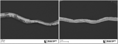
The leak was due to a circumferential crack located in one of the outer convolutes in the hose (Figure 3). The convolute containing the crack exhibited significant wear.
Figure 3. Circumferential crack observed in the inner convoluted pipe. Close-up examination revealed wear on the surface adjacent to the crack.


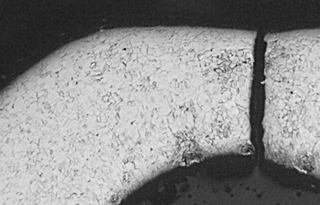
A cross-sectional sample was removed from the center of the crack and prepared for metallographic examination. Figure 4 shows a cross-sectional view of the crack. The apex of the convolute exhibited significant metal loss. The crack was relatively straight with a transgranular (through grain) morphology and no secondary cracking. No evidence of corrosion was observed on the flex pipe.
Figure 4. Cross section through the center of the crack.

Based on the evidence, the failure of the flex pipe was due to fatigue cracking. The straight transgranular cracks are characteristic of fatigue. The wear marks observed on the outer convolutes was due to the braided wire mesh rubbing against the flex pipe. The rubbing indicates that the flex pipe was exposed to significant bending loads. Excessive bending loads were known to be imposed during installation, and they combined with the normal operational cyclic loading (flow-induced vibration) to cause the flex pipe to crack.
Reviewing the installation revealed several issues that needed to be corrected. The piping was not properly supported to ensure that the flex pipe was not carrying any pipe loads. The flange holes on the flex pipe and piping were not properly aligned. And the mating flange surfaces were not parallel.
In order to avoid future fatigue failures of the flex pipes, it was recommended that the discharge piping in the unit be realigned. The approach taken to realign the piping and to help ensure better fit-up was to use a rigid flanged pipe section in place of the flex pipe. The rigid pipe section was installed in place of the flex pipe and the piping system was released from its constraints. The line experienced significant movement. After the movement, the piping system was secured in its new position. During this process, the piping was properly supported to minimize piping loads on the flex pipe. By using the rigid flanged pipe section in place of the reinstalled flex pipe for alignment of the piping, proper alignment of the holes was obtained and the flange surfaces were parallel. After the corrections to the piping system were complete, the flex pipe was reinstalled.
Related Posts