A small metallic particle that had contaminated a product line was brought to SI’s Materials…
Misinterpretation of Shock Wave Damage
By: Tony Studer
Slag consists of molten, partially fused or re-solidified deposits on furnace walls and other surfaces exposed to radiant heat in coal and other solid fuel fired boilers. Explosive deslagging is one method of dealing with slag buildup; however, if it is not performed correctly it can lead to damage in the boiler, including boiler tube failures.

Shock Wave Damage

Stress Corrosion Cracking
Shock loading of boiler tubes during the detonation of explosives typically occurs because 1) the charge size is excessive; and/or 2) the charge is not positioned properly relative to a tube in a given area of the furnace. In these cases, the shock wave produced by the detonation is intense enough to instigate brittle fracture in the tube wall. This type of damage can occur either internally within the tube wall or link to the ID or OD surface of the tubing, depending on the location of the shock wave. Secondary cracking that is not connected to the primary crack may also be present. These features are characteristic of shock wave damage; however, they are also associated with other damage mechanisms in steam side tubing, including creep and stress corrosion cracking (SCC). Results from various analyses of tubes with shock wave damage and other damage show how shock wave damage might be misinterpreted as another mechanism.
Shock wave damage, stress corrosion cracking damage, and creep damage can look remarkably similar, as shown in Figure 1. All three of the superheater tubes shown have a relatively straight, thick-edged crack. Therefore, visual examination alone is not enough to determine the damage mechanism for each of these tubes.

Creep Damage
Figure 1. These images show superheater tubes with relatively straight, thick edged cracks that were caused by different mechanisms.
Metallographic examination of the damage will reveal creep damage, which consists of voids, aligned voids, and micro-cracks, if it is present. However, shock wave damage and SCC can have similar appearances, even when prepared metallographic samples are examined using a metallurgical microscope, as shown in Figures 2 and 3.


Stress Corrosion Crack
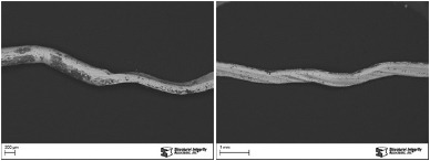
Figure 2. These images show cross-sectional views of a shock wave crack and a stress corrosion crack. While these images were taken at different magnifications, their appearances are similar.
Stress Corrosion Crack
Figure 3. These images show secondary cracks emanating from a primary fracture surface. Again, the magnifications are different but the branched cracks emanating from the primarily shock wave damage fracture surface could be mistaken for the branched cracking that is often associated with SCC.
Both shock wave damage and SCC can exhibit secondary branched cracking that may be difficult to differentiate. However, higher magnification examination of samples with shock wave damage generally reveals step-wise, secondary cleavage cracks (Figure 4). These small, step-wise cracks, which are relatively straight and at angles to each other, are generally only associated with shock wave damage.


Figure 4. Higher magnification views of shock wave damage cracks reveal the step-wise secondary cleavage cracks that are indicative of shock wave cracking.
Understanding the history associated with the tube samples is also important. If no explosive cleaning has been used in the boiler, then shock wave damage is not possible. However, shock wave damage does not always present itself immediately following explosive cleaning. Primary shock wave damage may not cause through-wall damage, and may leak after some time in service due to a different mechanism. If the shock wave damage created midwall separation, the stress level in the intact wall would be greatly increased. The increased stresses could lead to the formation of creep damage across the intact wall and eventually to failure. The combination of failure mechanisms could lead to misinterpreting shock wave damage as a creep failure.
Since shock wave damage can occur within multiple tubes located near any of the explosive denotation locations, ensuring reliable operation for units where damaged tubes have been identified requires removal of all damaged tubes that might remain in the boiler. Radiography is a reliable nondestructive method for finding damaged tubes (Figure 5). In addition, extreme care should be taken in the sizing and positioning of the charge to minimize the risk of the same type of damage during the future cleaning.
Related Posts