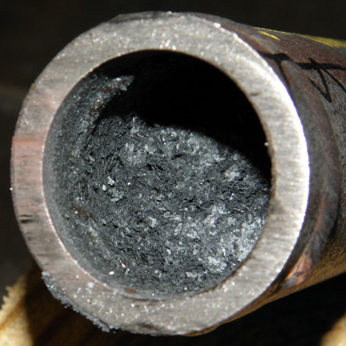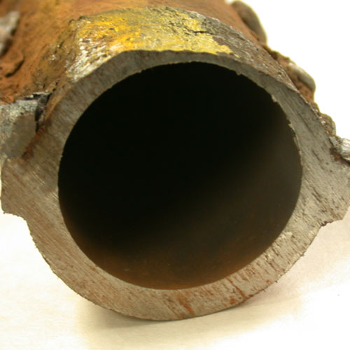
Toe Header Weld Crack
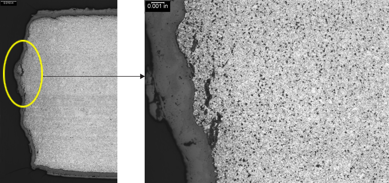
Crack surface of tube to header weld crack, which has a thick oxide layer and creep damage along its length
Creep-Fatigue
Introduction
Creep-fatigue is generally assumed to be the active mechanism when the rate of fatigue damage is influenced by the strain rate and hold times while the tube is operating at temperatures within its creep regime.
Description
Mechanism
Fatigue-dominated cracking is a response to the repetitive, or cyclic, imposition of stresses that under conditions of static loading would not be expected to cause significant damage. Creep-fatigue is essentially the accumulation of damage through synergistic interaction of cyclic stress and an elevated operating temperature. The creep and fatigue components of the damage usually occur at different periods in the thermal cycle. Cyclic loading may occur at temperatures within the material’s creep regime (≥800°F for Cr-Mo tubing). Once steady state conditions are reached, the component may continue to be exposed to high temperatures and localized stresses, which can result in the accumulation of additional plastic strains due to creep. Additionally, if residual stresses due to thermal transients were present, creep relaxation will add to the magnitude of the inelastic strain. The importance of creep-fatigue damage is that the fatigue life can be significantly less than would be predicted from pure fatigue test data.
Creep-fatigue damage can initiate at either the OD or ID surface of a tube, depending on the source of the loading, and because creep is a major component of the damage process the cracking can be predominantly intergranular. In austenitic tubing that has been thermally shocked by the impingement of a cooler fluid on the OD surface, for example during soot blowing, a state of stress can develop that will favor initiation of creep-fatigue cracking from the ID surface of the tube.
Typical Locations
- Superheater and reheater tubes where tube metal temperatures are in the creep regime
- Welded connections
- Bends
- Tube-to-header attachments
Features
- Generally initiates on the OD surface
- Typically single cracks
- Cracks are generally relatively straight, relatively wide, and oxide filled or oxide lined
- Creep voids and microfissures can surround the primary crack, but creep damage does not have to be present.
Root Causes
Creep-fatigue is caused by the interaction of stresses, both cyclic and static, and elevated temperature exposure. Root causes can include excessive stresses/strains, excessive tube temperatures, and unit operation.
Excessive stresses/strains can result from the following, many of which are related to HRSG operation: constrained thermal expansion, pressure changes, fluid temperature changes, non-uniform temperatures, load transfer between hot and cold conditions, changes in external loads, transient temperature differences, steam or water hammer, forced vibration, flue gas flow problems, thermal transients due to condensate flashing into tube circuits, improper attemperation, and incorrect or inadequate drains.
Excessive tube temperatures can result from excessive temperature ramp rates, poor distribution of tube temperatures, poorly designed thickness transitions at header connections and supports, and poor material selection for tubing.
The number of service hours, number of stop/starts, and the characteristics of the stop/starts are unit operation influences that can affect creep-fatigue damage.
Corrective Actions
Once creep-fatigue has been confirmed as a damage mechanism, it is important to determine the extent of the damage. Since this damage typically initiates on the OD surface of a component, all of the standard non-destructive inspection techniques, including visual examination, dye penetrant inspection, and wet florescent magnetic particle inspection, can be used effectively to detect creep-fatigue damage. The one exception to this is thermally-induced creep-fatigue damage in austenitic stainless tubing, for which enhanced ultrasonic inspection techniques are the most effective means of detecting the damage.
Cracks can usually be ground out and rewelded as a temporary repair; however, tight bends should be replaced. The key to long-term mitigation of creep fatigue is a coherent strategy that begins with understanding the root cause. Thermocouples can be used to quantify the magnitude of tube-to-tube temperature differences, and strain gauges can indicate whether strains that develop at specific locations during periods of transient operation are sufficiently high to instigate creep-fatigue cracking, or whether at a particular location there are tensile residual stresses in the component of sufficient magnitude to promote creep-fatigue cracking. Operational and/or design changes may be necessary parts of long-term solutions.
SI Services
- Mechanism verification through destructive metallurgical analysis
- Determination of the root cause of cracking as a basis for identifying the appropriate corrective action
- Non-destructive inspection of tubing to identify cracking
- Assistance with repair/replacement action