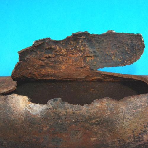
Showing OD wastage
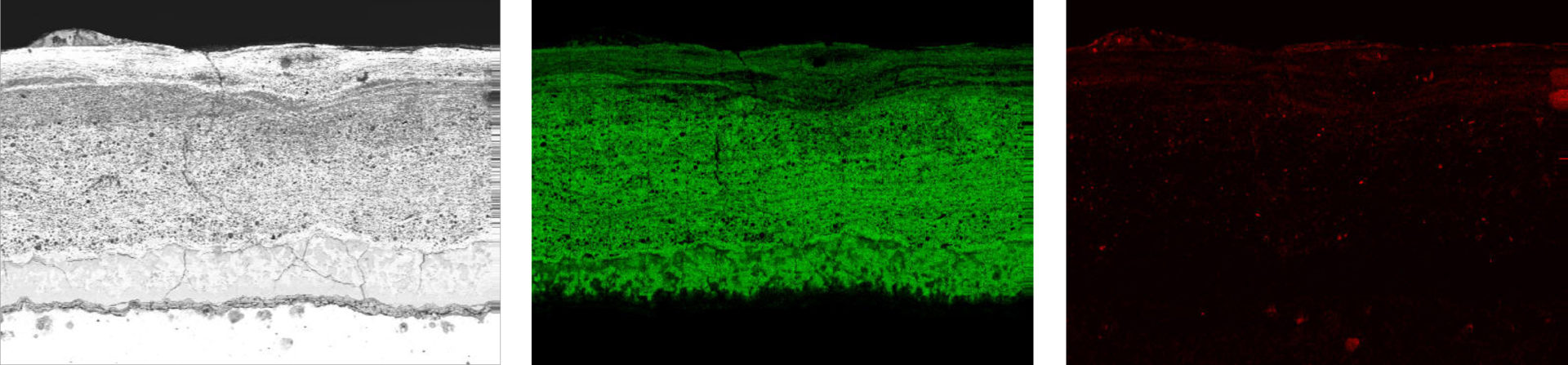
An SEM image and elemental mapping of OD deposits from a tube with fireside corrosion, showing sulfur (green) and carbon (red) throughout
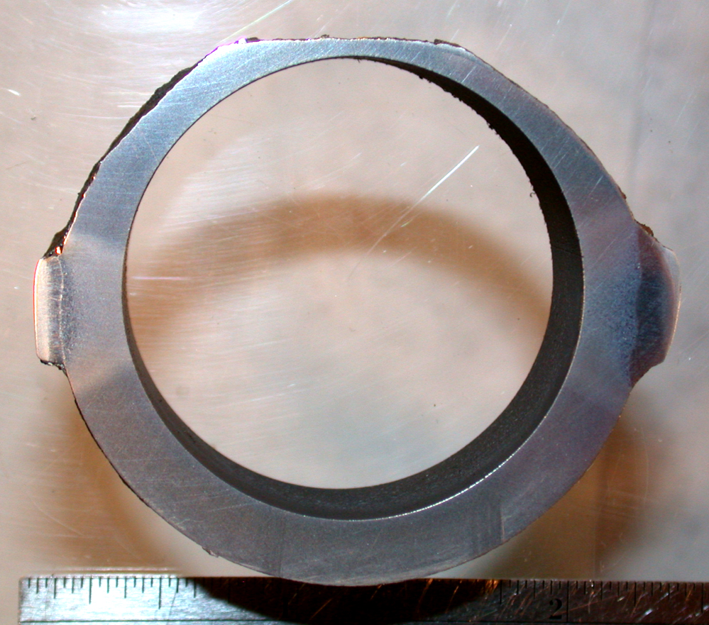
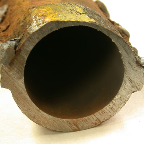
Ring section through area adjacent to rupture showing external wastage around hot side of tube with most severe wastage at crown of tube
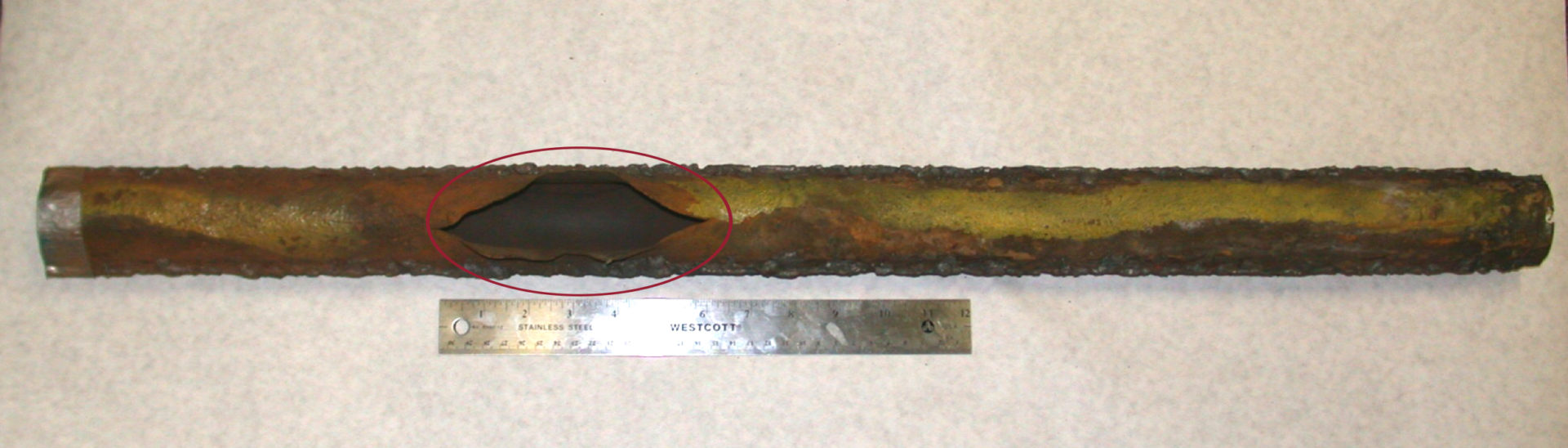
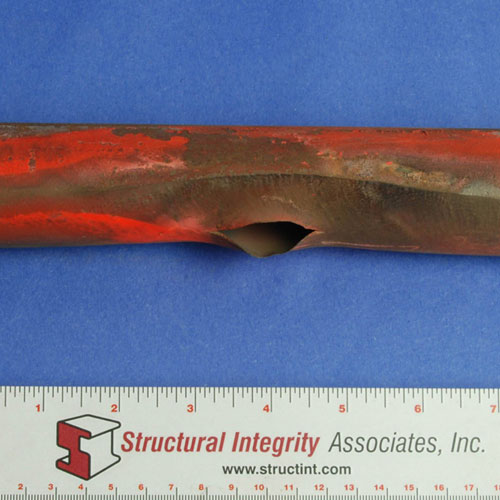
Thin edged rupture due to fire side corrosion
Waterwall Fireside Corrosion
Introduction
Industry experience shows that waterwall tubing in conventional boilers can be susceptible to fireside corrosion, depending on fuel type, firing practice, etc. In boilers where fireside corrosion has been identified as a maintenance issue, wastage rates of 5 to 25 mils/year are not uncommon. Since the mid 1990s, the installation of low NOx burner systems designed to lower NOx emissions has significantly increased the wastage rates in some boilers. Operators of subcritical boilers have reported wastage rates as high as 30 mils/year, while those operating supercritical boilers have reported rates exceeding 100 mils/year in the worst cases. These higher damage rates have resulted in an increase in tube failures, and operators have struggled to accurately define the extent of the damage and install the appropriate mitigating technologies.
Description
Mechanism
Fireside corrosion is an extraordinarily complex phenomenon due to the number of chemical and physical reactions that influence the damage process. Two important contributors to the damage are corrosive species in the fuel, such as sulfur and chlorine, and the local furnace environment, including the composition of the furnace gases, the composition of the slags that form on the walls as a by-product of combustion, and the tube metal temperatures.
There are three primary mechanisms for fireside corrosion: sulfidation by iron sulfides (pyrites), gaseous corrosion by hydrogen sulfide, and corrosion by alkali chlorides that are produced from gaseous hydrogen chloride. All of these occur in reducing or alternating reducing/oxidizing conditions. Unburned carbon, iron oxide and iron sulfide found in scale overlaid by sintered deposits are typical signs of “poor combustion” and locally reducing environments. Low NOx firing technologies (burners and staged air), by design, stage combustion and create a reducing environment in the lower furnace.
The corrosion rates vary widely as each mechanism is influenced by elemental concentrations and temperature. Tube failures due to fireside corrosion are the direct result of loss of wall thickness, which causes an increase in the hoop stress of the thinned tubes, usually culminating in a longitudinally-oriented thin-lip rupture.
Typical Locations
Due to the influence of the local environment on the extent and severity of the corrosion, the location of damage can vary significantly depending on boiler type and firing system design. Fuel and air nozzle position and condition, coal particle size, and the location of the areas of highest heat flux all are variables which can determine where corrosion occurs and how severe the rate of attack will be.
- Wall fired boiler: the damage usually is concentrated on the side walls from mid burner elevation upward. Front and rear walls may also exhibit corrosion, but usually the wastage rates are much lower.
- Tangentially fired boiler: the greatest wastage rates are typically on the front and rear walls, with the side walls showing much lower rates of attack. The most severe damage often is found from the upper burner elevations into the separated overfired air ports and generally is more predominant in the “hot corners”.
Features
- The wastage often is most severe at the crown of the tube, but damage can extend to the entire fireside surface of the tube and the adjoining membrane, if present.
- Tubes that have suffered severe attack will often be covered by a deposit with a hard, dense black layer at the tube metal interface and a layer of soft, loose ash on the outside.
- The external surface usually exhibits an irregular surface beneath the deposits that have a dimpled or “alligator hide” appearance.
Root Causes
Broadly speaking, increased tube metal temperatures and corrosive species are the root cause of this mechanism. More specifically, coal composition and the boiler firing system can promote and introduce corrosive species local to the fireside of the tube. Increases in sulfur and chlorine in the fuel as well as the introduction of substoichiometric conditions due to low NOx firing technology, improper mill performance, improper fuel/air mixing, and worn burners promote an increase in corrosivity. Elevated tube metal temperatures may result from flame impingement, internal deposits, restricted water flow or an increase in the local heat flux due to the firing system. In addition, carbon deposited on the fireside as a result of flame impingement or poor mill fineness aggravates the damage.
Corrective Actions
A thorough visual and/or tactile examination can identify areas with significant fireside corrosion damage. However, where only minor attack has occurred the damage may go undetected. The amount of damage can be quantified with ultrasonic thickness testing. This data is valuable in determining not only the remaining wall thickness but also for establishing corrosion rates and setting reinspection intervals or scheduling replacements. Because conditions can vary significantly between different locations on the furnace walls, leading to substantial variability in the distribution of damage, it is important to perform a thorough inspection to ensure that the areas with the highest wastage rates (and not average rates) are identified and addressed to prevent future tube failures. Typically ultrasonic thickness data is taken on grids covering areas of the waterwalls. The grid size for the first cut is typically large to allow covering more of the walls. Once this data has been reviewed along with visual inspection information, the need for smaller inspection grids may be required to determine the extent and severity of the damage at specific locations.
Once sufficient thickness data has been obtained, the remaining life of the tubing should be estimated based on the apparent wastage rates. This will define the severity of damage and the impact on overhaul schedules, and it will assist in identifying the appropriate remedial actions. Depending upon the root cause of the wastage, and in consideration of the boiler operating protocol, mitigation may involve any one of the following, either alone or in combination: operational changes, fuel changes, pulverizer tuning, cycle chemistry adjustments, design modifications to burners and air ports, and the application of corrosion resistant materials. The appropriate corrective actions for a given boiler will depend on factors such as the root cause, the geography and rate of damage, when the damage is identified, and the amount of available outage time and funding. In the short term, damaged tubing can be replaced in kind or the thinned tubes can be pad welded with a matching composition, or weld overlayed with a more corrosion resistant material.
If no other changes are instituted, replacement in kind or pad welding with a matching composition merely resets the clock and future failures can be expected, so these steps should not be considered unless necessary to bridge operation until a more convenient outage time. Long term actions should focus on changes to the operation of the unit that would modify the local environment to eliminate the corrosion potential. Where that is deemed impractical, other actions that may substantially increase the service life of the tubing under the corrosive conditions would include increasing wall thickness, shop or field application of protective coatings, diffusional modifications of tube surface chemistry, or making material changes such as co-extruded tubing or, in supercritical units, nickel-base tubing. The protective coatings would include both weld applied overlays and thermal spray coatings. In general, coating materials which provide deposit chemistries with more than 20% chromium are effective in combating the wastage. It is emphasized that an understanding of the root cause of the wastage is essential if the appropriate protection system is to be selected. All of the commonly used corrosion resistant weld overlays have relatively low thermal conductivities, so that with the greater wall thickness the surface tube metal temperatures will be increased, which can promote circumferential thermal fatigue damage, especially in supercritical boilers. Prior to selecting a remedial strategy, both the root cause of the corrosion and the severity and extent of the attack should be determined. Additionally, the potential ramifications of the implementation of the remedial strategy should be thoroughly understood to avoid unintended consequences that could lead to tube failures.
SI Services
- Plant operational reviews and benchmarking of damage severity. Reviews not directed toward specific concerns such as fireside corrosion can identify attributes which need improvement to avoid susceptibility to fireside corrosion and other forms of waterwall damage.
- Laboratory analysis of damaged tubing to assess condition and determine responsible damage mechanism.
- Cycle chemistry assessments especially on supercritical plants.
- Evaluation of possible root causes of damage to determine the effective causes(s) requiring action by plant staff to prevent continued damage and failures.
- Assess plant practices with respect to a series of Repeat Situations which, if not corrected, are known to substantially increase the risk of fireside corrosion damage.
- In situ assessments to identify damaged tubing.
Additional information
| Boiler Type | |
|---|---|
| Fuel | |
| Boiler Region | |
| Metallurgy | |
| Failure |