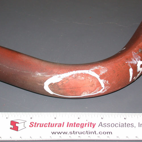
Circumferential crack
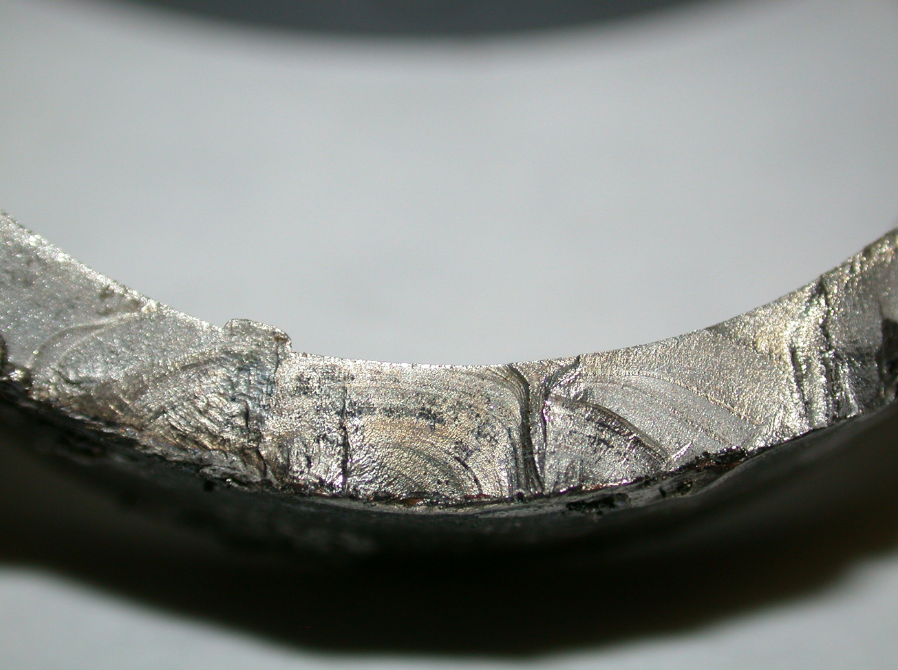
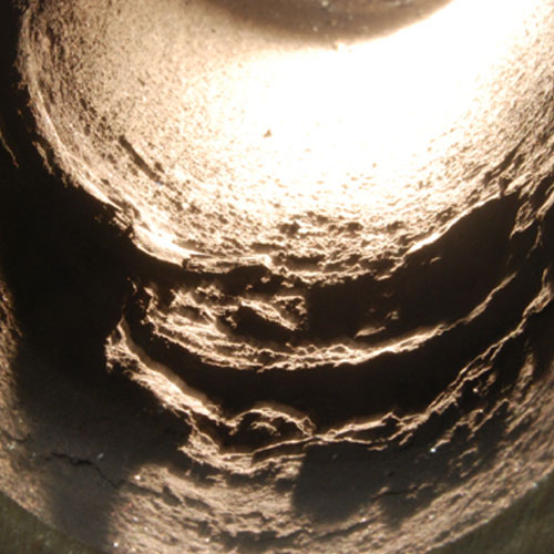
Figure 2. Beach marks observed on fracture surface
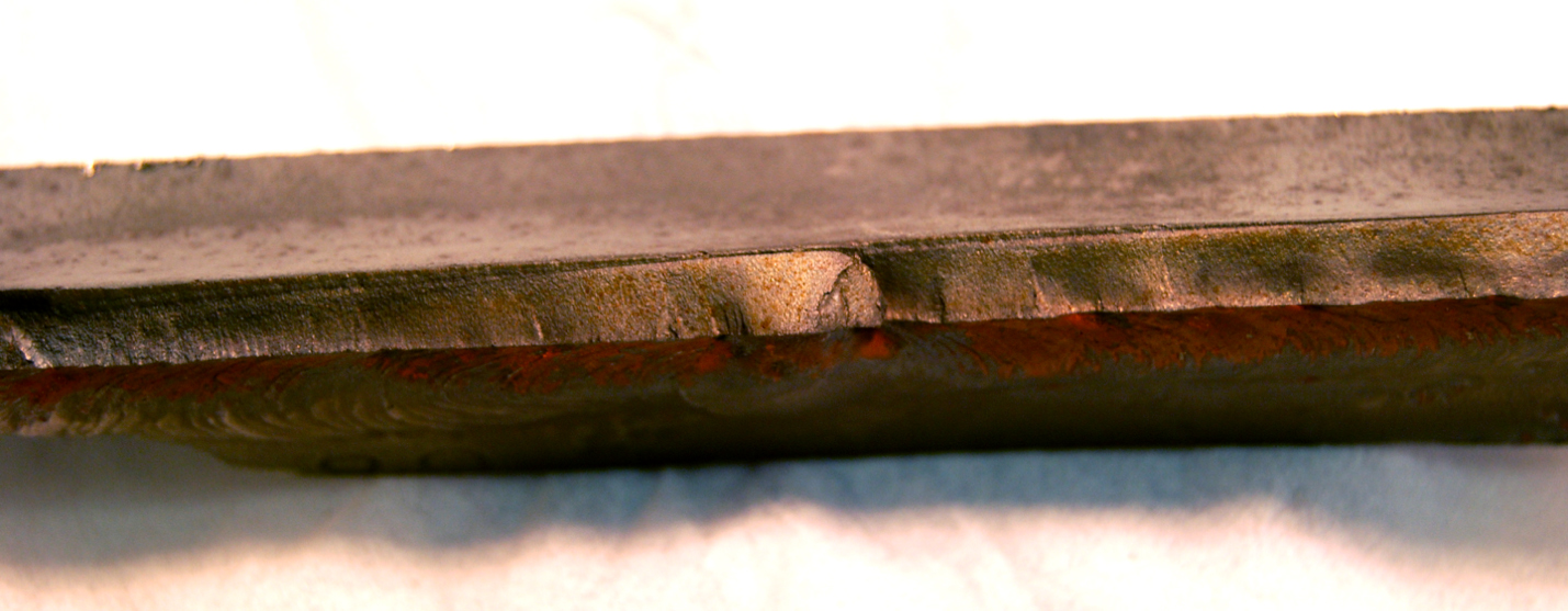
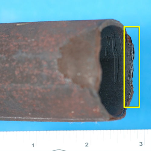
Figure 3. Tube with longitudinal fatigue crack at attachment and corresponding fracture surface B
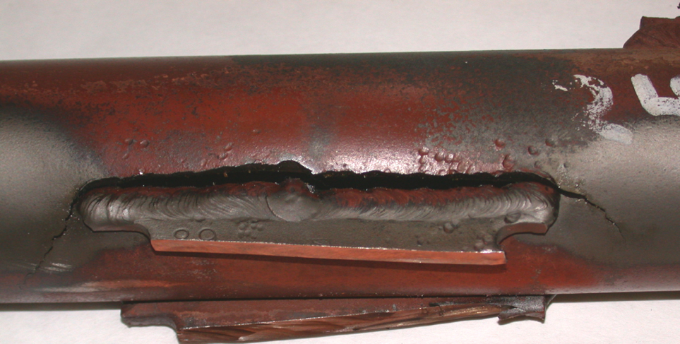
Figure 3. Tube with longitudinal fatigue crack at attachment and corresponding fracture surface
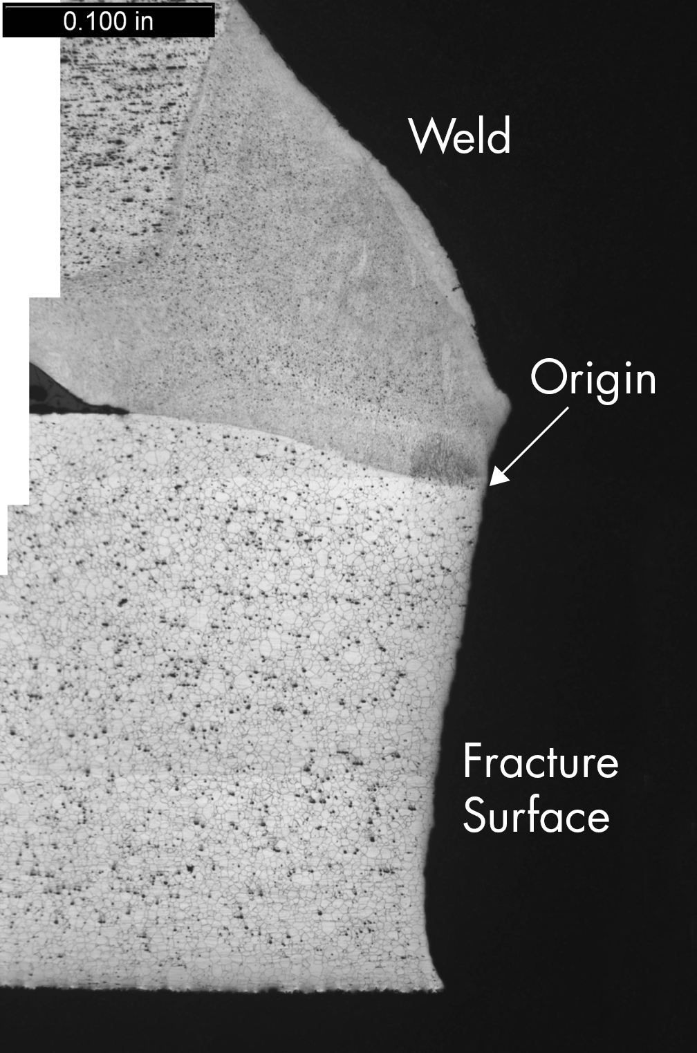
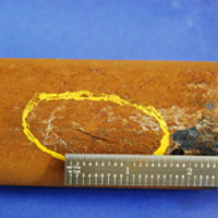
Figure 4. Cross-section showing flat transgranular fracture that initiated at toe of attachment weld
Thermal and Mechanical Fatigue
Introduction
Thermal and Mechanical Fatigue in Boiler Tubing
Thermal and mechanical fatigue is an important boiler tube failure mechanism in which the damage initiates on the outside of the tube at locations of constraint.
Description
Mechanism
Thermal and mechanical fatigue is a discontinuous failure mechanism. The fatigue cycle is driven by excessive local stresses imposed on the tube only during certain operating spaces. The stresses may be induced by a) excessive mechanical loadings, b) restrained thermal expansion, c) vibration, and d) poor weld geometry. During normal full load operation the strain in the tube is very low, and only during certain operating regimes does the strain locally increase due to the restriction in expansion caused by the attachment. Experience has shown that these regimes may be related to operation features (startup, shutdown, forced cool, transient operation, trips) or due to mechanical loading by other boiler equipment (mill operation, coal pipes, burner equipment).
Typical Locations
The areas that are most vulnerable to thermal and mechanical fatigue failures are those locations where the tubes are restrained from movement, including welded tube-to-tube attachments and tube-to-header welded connections (the final SH and RH headers in HRSGs are particularly prone to this damage). The fact that in most of these cases the cracking initiates at the toe of the attachment weld reflects the stress concentrating effect of the geometric discontinuity of the weld toe. Fatigue failures also can occur at bends, particularly at tight-radius bends, when there is unequal growth in the legs of the bend due to an unequal mix of austenitic and ferritic material in the two legs or when one leg is more rigidly constrained than the other leg. The primary locations in the waterwall are nearly always associated with attachments (around man-door openings, hopper attachments, burner nests, buckstays, tie straps etc.) or at end of membranes (slope tubes).
Features
- Pinhole leak or circumferential crack at toe of attachment weld
- Beach marks and fatigue striations on fracture surface
- Flat transgranular (through grain) fracture surface
- Cracks are generally relatively tight and straight
- Fracture surface may have thin oxide layer
Root Causes of Thermal and Mechanical Fatigue
There are a number of potential root causes for thermal and mechanical fatigue failures in boiler tubing. The most common include: (1) restraint of movement during thermal expansion; (2) differential relative movement due to differences in temperature between connected tubes; (3) flow-induced vibration; (4) excessive stresses; and (5) workmanship type defects. In some cases the orientation of the cracking, the surface appearance of the failure area, or the microstructural appearance of the cracking can provide enough information to determine which of the root causes is involved. In most cases, however, supplementary testing should be performed to identify with certainty the cause of the damage.
Thermocouples can be used to quantify the magnitude of tube-to-tube temperature differences, and strain gauges can indicate whether strains that develop at specific locations during periods of transient operation are sufficiently high to instigate cracking, or whether at a particular location there are tensile residual stresses in the component of sufficient magnitude to promote fatigue cracking.
Corrective Actions
Liquid penetrant, magnetic particle, eddy current, ultrasonic testing, and radiography can all detect cracks on the external surface. Linear phased array can be used to size cracks.
Thermal and mechanical fatigue is most often repaired by an in-kind replacement and sometimes by grinding out the cracks and pad welding. These processes do not address the root cause of the mechanism, and thus the mechanism will return and continue as a repeat boiler tube failure (BTF). The optimum process for replacement involves designs which reduce the imposed strain to below the fracture strain, but most often the permanent solution involves modifying the damaging operating space.
SI Services for Thermal and Mechanical Fatigue in Boiler Tubes
- Mechanism verification through destructive metallurgical analysis
- Determination of the root cause of cracking as a basis for identifying the appropriate corrective action
- Non-destructive inspection of tubing to identify cracking
- Assistance with repair/replacement actions
Additional information
| Boiler Type | |
|---|---|
| Fuel | |
| Boiler Region | |
| Metallurgy | |
| Failure |