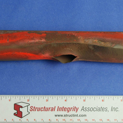
External surface of waterwall tube with corrosion fatigue crack on code side of tube indicated in yellow box
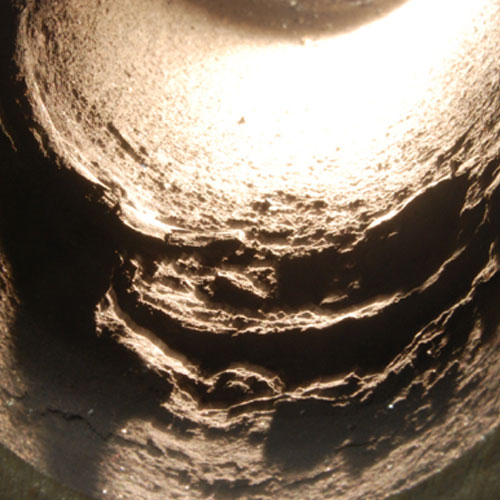
An array of corrosion fatigue cracks emanating from the internal surface
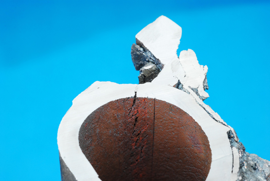
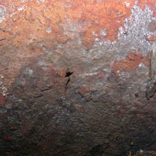
End view of an area of cold side cracking between a membrane weld and an attachment weld. Also note the straight mandrel mark
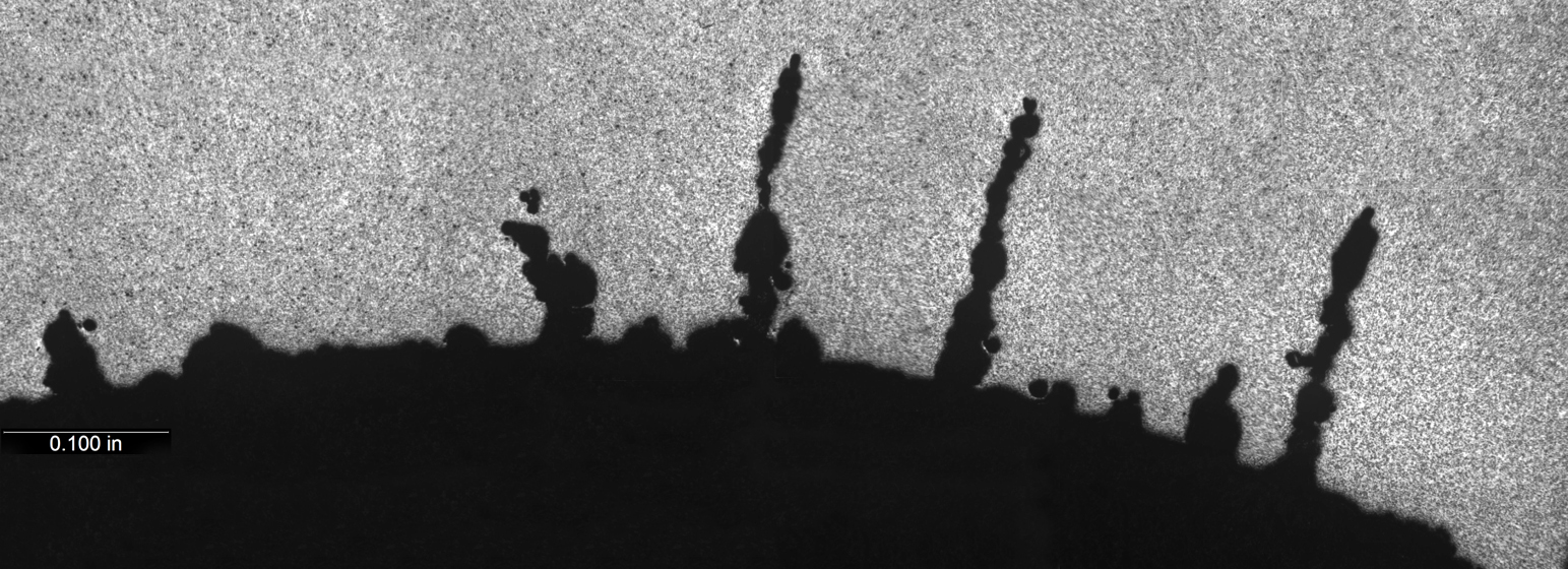
Metallographic cross-section from an area with corrosion fatigue. Note the multiple cracks on the ID surface around the through wall crack

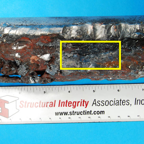
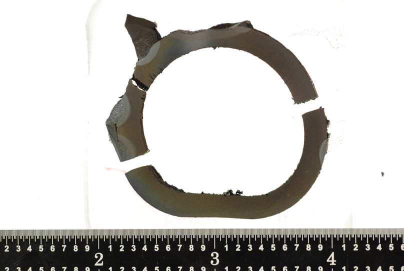
Window section removed from hot side of tube to reveal the internal surface on the cold side. Numerous cracks are present
Corrosion Fatigue
Introduction
Corrosion fatigue is a major repeat boiler tube failure mechanism in conventional fossil plants. It is initiated on the inside tube surface, reflecting the cycle chemistry contribution to the mechanism.
Description
Mechanism
Corrosion fatigue is a discontinuous failure mechanism that propagates through the tube wall by a repetitive oxide fracture mechanism. The magnetite that grows indigenously on the inside tube surface is a protective oxide, unless it is subjected to strains in excess of its fracture strain (about 0.2%). Periodic cracking of the oxide exposes the tube metal to localized re-oxidation, creating a fatigue-like advancement of the crack. During normal full load operation the strain in the tube is very low, and only during certain operating regimes does the strain locally increase due the restriction in expansion caused by the attachment on the cold side. Experience has shown that these regimes may be related to operational features (startup, shutdown, forced cool, transient operation, trips) or due to mechanical loading by other boiler equipment (coal pipes, burner equipment). The boiler chemistry is also known to exacerbate the corrosion fatigue mechanism and rate, with the most important parameter being the reduction in the boiler water pH from normal operating ranges. Situations in which the pH is depressed at the same time that peak strains are imposed on the oxide are particularly harmful and need to be identified.
Typical Locations
- Attachments on the cold side of waterwall tubing.
- Along the membrane weld either on the fireside or coldside* of the tubing.
*The cold side failures are a serious safety issue because in many cases the tube unzips and opens out like a window, releasing large amounts of high temperature steam that can blowout the boiler casing.
Features
Initiates on the internal surface and emanates to the OD surface as:
-
- a pinhole leak (most common)
- a thick-edged crack oriented either axially or circumferentially
- a thick-edged rupture on the hot or cold side of the tube
- Multiple, transgranular cracks that are usually wide, oxide filled and blunt tipped with corrosion bulges along their lengths, which are evidence of discontinuous propagation
Root Causes
There are multiple possible root causes of corrosion fatigue that relate to either operating spaces or mechanical loading. Corrosion fatigue can only be solved by identifying which root cause is harmful, eliminating it and thus eliminating the mechanism. Identifying the root cause involves: a) clearly identifying the geography and history of failures, utilizing NDE inspections, as necessary; b) monitoring the temperature/strain history at vulnerable locations, which typically involves attaching thermocouples, strain gauges, LVDTs or potentiometers to the tube locations and/or non-pressure part attachments near to CF cracking; c) a review of cycle chemistry and chemical cleaning history; d) parallel cycle chemistry monitoring of the current program to identify whether the pH is depressed during harmful operating spaces; e) finite element analysis of the locations monitored to determine if the strain on the ID tube surface exceeds the fracture strain; and f) modifying the operating space or mechanical loading to ameliorate the fracture strain.
Corrective Actions
SI uses a two-level approach to identify and quantify corrosion fatigue cracking. The first level, which focuses on a determination of the geography, can involve radiography, digital radiography, visual examination (fiber optics if there is internal access, since cracks can clearly be seen visually), and, depending on the location, linear phased array (LPA). The second level, in which the CF cracks are sized, involves LPA or tube sampling.
Corrosion fatigue is most often repaired by an in-kind replacement. Less frequently, grinding out the cracks and pad welding is done, but this is not considered a good long-term repair method. Corrosion fatigue failures will return and continue as a repeat failures until the root cause is addressed, as described above. The optimum process for replacement involves designs which reduce the imposed strain on the oxide to levels below the fracture strain.
SI Services
- Compilation of the geography and history of corrosion fatigue failures and damage on a boiler.
- NDE/inspection services to define the geography of damage.
- Mechanism identification through comprehensive metallurgical analysis of the failure situation and/or morphology of the internal indigenous oxide and deposits.
- Plant chemistry program reviews and benchmarking, typically completed during a one day site visit. Reviews not directed toward specific concerns can identify program attributes that need improvement to avoid susceptibility to other chemistry influenced damage and failure around the cycle.
- Evaluation of possible root causes for the particular boiler and derivation of road map approach to determine actual root cause. This may involve monitoring the boiler through all the historical operating spaces, and conducting finite element stress analysis to identify the strains imposed on the tube ID.
- Suggesting modified operating spaces and/or mechanical loading followed by conducting repeat monitoring to determine if they reduce the imposed strains to below the fracture strain of magnetite.
- Provide advice and guidance on repair aspects.
Additional information
| Boiler Type | |
|---|---|
| Fuel | |
| Boiler Region | |
| Metallurgy | |
| Failure |